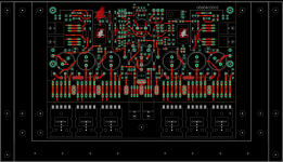
Finished the conversion with excellent results. Probably cheaper all up than using transformers. I wasn't game to try with the 8x10,000uF back end PS caps in place so I removed them - less startup stress on the SMPS. I used a 500W LLC PS from Aliexpress. It was nominal +/-36V as ordered, reduced to +/-34V by adding a 910K in parallel with R66 (back of main PCB). A CL60 mounted on a porcelain block was used to connect 0V to the chassis. If you order make sure you get one with a black heatsink which has two tapped M3 holes which allow fitting of an additional heatsink (well worth doing as it then runs just hot to touch with lid on). This SMPS also puts out +/-15v unregulated which powers the front panel pilot LED and a basic 7812/7912 regulator PCB for power to the Sparkfun THAT1206 balanced to single ended converters.
For the FE shunt PS applicable diodes were replaced by links to allow DC input. The 2200uF filter caps were removed as the caused hiccupping with the Meanwell PSs. 47uF caps were used in place. The meanwells are nominal 48V SMPS but are adjustable about +/- 10% such that the input voltage to the FE shunts can be optimally trimmed to minimise dissipation.
Parts used : LLC SMPS https://www.aliexpress.com/item/32846308063.html?spm=a2g0o.order_list.0.0.21ef18029i4zZq
THAT1206 : https://www.sparkfun.com/products/14002
Meanwell SMPS for FE shunt : https://www.x-on.com.au/mpn/meanwell/rs1548
Additional heatsink : https://www.jaycar.com.au/high-effi...574b7034beb32ae19b942e3d030431&sort=relevance
+/-12V regulator PCB : https://www.jaycar.com.au/universal-power-supply-regulator/p/KC5501
Last edited:
switchover of two amplifiers (class D and this) , for listening ?when switching speakers during operation?
I would turn it off first
No, changing speakers during operation.switchover of two amplifiers (class D and this) , for listening ?
I would turn it off first
I have another problem now on the left channel - output bias current fluctuates quite a lot, and left heatsink gets rapidly hotter than the right one. Voltage across output resistors fluctuates between 18mV and 51mv very quickly, and does not appear to react to trimmer rotation. No change in behavior from cold start to warm. Front end PS voltage is stable at +-39V.
Wellcome to oscillation area...I have another problem now on the left channel - output bias current fluctuates quite a lot, and left heatsink gets rapidly hotter than the right one. Voltage across output resistors fluctuates between 18mV and 51mv very quickly, and does not appear to react to trimmer rotation. No change in behavior from cold start to warm. Front end PS voltage is stable at +-39V.
Check/replace VAS/Bias stagesoutput bias current fluctuates quite a lot, and left heatsink gets rapidly hotter than the right one. Voltage across output resistors fluctuates between 18mV and 51mv very quickly, and does not appear to react to trimmer rotation.
Never mind, bad contact on diode string...I have another problem now on the left channel - output bias current fluctuates quite a lot, and left heatsink gets rapidly hotter than the right one. Voltage across output resistors fluctuates between 18mV and 51mv very quickly, and does not appear to react to trimmer rotation. No change in behavior from cold start to warm. Front end PS voltage is stable at +-39V.
I have been using two of these amps for 10 years now. There have always been a minor "pop" during power on/off cycles in most of the cases, but recently I have started witnessing some quite unpleasant audio artifacts which probably mean that output stage is offloading to speakers. Has anyone implemented any speaker isolation during power ups/downs? I am still also experiencing fuse blows occasionally on cold start, even though I am using T4A slow blows.
Of course I can, but I am looking for experiences from those who already did it. I have a PGA Pre preamp with Arduino in the same case already, so it's not going to be too difficult. I also plan to include temp sensors from both heatsinks.Use powerful relay to delay the start!
I use a soft start and also a speaker protector with delay. It has been running for a few years without a problemOf course I can, but I am looking for experiences from those who already did it. I have a PGA Pre preamp with Arduino in the same case already, so it's not going to be too difficult. I also plan to include temp sensors from both heatsinks.
- Dan
This amp was virtually noiseless over the years (except for power up/down, but that will be taken care of with speaker switches I designed). I am basically using 2 monoblock configuration, with chassis not connected to power ground. However, with return of the vinyl, I wanted to put a phono amp inside, and that's were problems started. All other inputs are still quiet, but phono is loaded with buzz. So I was wondering what grounding scheme are people here using? I have chassis connected to 230V ground only, so 2 separate power/audio grounds are floating.
- Home
- Amplifiers
- Solid State
- RMI-FC100, a single stage audio power amplifier
