hello all
im building the fc100 with a front end power supply that needs to be set with the correct output voltage .does anyone know what the front end voltage is?
im also considering using this regulated supply for the back end power as well..what do you think,good idea or not?....https://www.amb.org/audio/sigma22/
Last edited:
thanks lordoff and zdr
the built in circuitry of the front end will draw 21.5ma from the supply at idle correct?
the thing i like about this power supply for back end power is the almost non existent ESR of traditional caps and extreme low noise .....10uV
i think with good heatsinking it would be ok,
the built in circuitry of the front end will draw 21.5ma from the supply at idle correct?
the thing i like about this power supply for back end power is the almost non existent ESR of traditional caps and extreme low noise .....10uV
i think with good heatsinking it would be ok,
thanks lordoff and zdr
the built in circuitry of the front end will draw 21.5ma from the supply at idle correct?
the thing i like about this power supply for back end power is the almost non existent ESR of traditional caps and extreme low noise .....10uV
i think with good heatsinking it would be ok,
There is only one review on eBay for this power supply,
Sigma22 Linear Regulated Power Supply PSU kit for Preamp headphone amp 699903972400 | eBay
translated from russian:
"I do not advise buying from this seller, it does not supply quality components, the photo shows completely different elements (from well-known brands), and the package contains cheap Chinese components, if I knew that there would be such components I would never buy this product. I do not recommend it."
Also this:
"Configurable for rail voltages up to ±36V. The voltage is selected by using an appropriate reference zener diode, and choosing the value of a resistor. No further adjustment is needed.
Typical output voltages are ±5V, ±9V, ±10V, ±12V, ±15V, ±18V, ±24V, ±27V, ±30V or ±36V. These are popular voltages specified for many headphone amplifiers, preamplifiers, and class-AB power amplifiers up to around 20Wrms power output into 8Ω."
Last edited:
i am careful not to source anything from ebay or china,i got the board and some components directly from AMB audio(high quality board),for the remaining components i will source from mouser or the like.
after further consideration,i have decided not to use this power supply for the back end but for the front end only. the question remains should i use 1supply for both channels or 1 for each channel.
after further consideration,i have decided not to use this power supply for the back end but for the front end only. the question remains should i use 1supply for both channels or 1 for each channel.
i am using this power supply because the one i have from Rudi i used for solder practice, i thought i would be able to remove the solder after wards but that didnt go so well..so in the mean time i didnt want to wait so long for a new board from abroad so i got this one from AMB audio. my intention wasn't to try to improve or change anything ...but this power supply is a step up from using one with ic's.
i didnt want to admit what i did to the board with the soldering practice, but you asked a lajit question..WHY?.so there you go.
i didnt want to admit what i did to the board with the soldering practice, but you asked a lajit question..WHY?.so there you go.
My question is why? The original design is already as good as it gets, and you will never know if you improved anything if you haven’t tried the original first.
Hi ZDR,
How did you find the sound & performance with the LT3062 based supply in comparison to the Shunt regulator ?
I notice the LT3062 has a very low rms noise figure.
-Dan
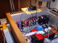
Jaack, when Mihai designed the FC-100 (his 1st post revealing the FC-100 amplifier is from November 2007), the Linear Technology LT3062 voltage regulator
has not yet been "well-known", and I suppose that this is the reason why Mihai designed a shunt regulator (the "Non-Plus-Ultra" at those former days)
to provide power to the FC-100 frontend.
My 1st FC-100 - build used exactly this frontend (see attached Image 1).
Current regulators like the TPS7A47 (for "low" Output voltages) or the LT3062 (for output voltages up to > 40VDC) provide low output current (< 200mA in
case of the LT3062) with "extremely low noise" on the output voltage (30µVRms).
I have abuilt a dual LT3062-based frontend PSU (giving about +/- 38VDC) (for test purposes) and have compared it to Mihais shunt.
I do not "hear" any difference.
On the picture below: Mihais shunt Regulators is placed in front of his FC-100, the LT3062 is put on top of the heatsink.
A "nice-to-have" side-effect: you only need 1 (!) dual LT3062 - PSU in contrast to 2 (!) shunt regulators for a dual-channel FC-100.
I am sad to hear that you have wrecked my LT3062 PSU - PCB.
But: do not give up and learn how to solder.
The FC-100 is worth every cent that you investigate.
Best regards - Rudi
Attachments
Last edited:
Rudi
i was hoping some how you would miss reading my post about the soldering practice,i am now also sad that you are sad,you are one of the nicest guys here on diyaudio,i, like many others appreciate you being here and all that you do.
on the bright side of things,i have started the assembly of the power supply and soldering is turning out to be easier then i thought, i am getting expert looking solder joints.i was worried for nothing. using the correct tip,solder wire size and flux makes all the difference.i will be posting pictures when i get further along in my progress.
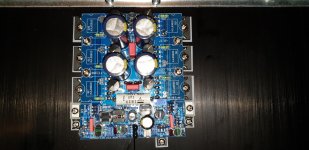
I tried making this project as easy as possible for everyone. My pcbs have printed component values to reduce possibility of errors, and have separate main amp pcb from capacitor bank with rectifiers, which allow for more flexibility for heatsinks placements. There is also a document with compiled advices from this thread, in the link in my signature.
Hi All,
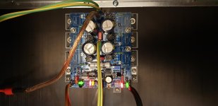
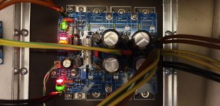
I just built the RMI-FC100 using Zdrs boards.
The power supply works well but when testing the front end the negative rail
Is loaded down too much only Q6,Q7 and Q10,Q15 pairs are hot to touch, all leds light up. Does any one have any ideas what may cause this... pic attached
I just built the RMI-FC100 using Zdrs boards.
The power supply works well but when testing the front end the negative rail
Is loaded down too much only Q6,Q7 and Q10,Q15 pairs are hot to touch, all leds light up. Does any one have any ideas what may cause this... pic attached
Attachments
Hi All,
I just built the RMI-FC100 using Zdrs boards.
The power supply works well but when testing the front end the negative rail
Is loaded down too much only Q6,Q7 and Q10,Q15 pairs are hot to touch, all leds light up. Does any one have any ideas what may cause this... pic attached
Dan, without knowing your voltages this is what I would do:
1. Check Vbe voltages across all transistors above and voltage points (see RMI FC100 doc on my site)
2. Check if all transistors are of correct type (NPN/PNP)
3. Check resistor values
4. Compare with other channel - is it behaving the same way? If not, where is the difference?
Last edited:
Ok finally Success ! I had a solder bridge on a very small solder pad on the input.
Happy to say I was listening to the first channel last night.
First impressions are very good!
DC offset is only 2.4 mV, bias is 200mA per transistor,
Can't wait to case it up
Happy to say I was listening to the first channel last night.
First impressions are very good!
DC offset is only 2.4 mV, bias is 200mA per transistor,
Can't wait to case it up
Attachments
RMI-FC100 working !
.jpg")
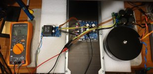
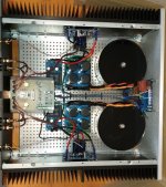
A couple of build pics for this one, it is running and I am super happy with the sound.
I am running 200 mA bias per output transistor.
DC offset is 1 or 2 mV cold and 0.5 mV warm.
AC ripple on the output (hum) is below 100uV rms with no input.
The amp is so quiet you cannot tell if it is on with no signal applied with an ear on the speaker.
The sound quality is excellent, in comparison with JLH, Hiraga, Krell clone mono blocks, it really is a great design.
Credit to Mihai Ruata's design work and credit to Neb (ZDR) for the compact board design.
Attachments
")
- Home
- Amplifiers
- Solid State
- RMI-FC100, a single stage audio power amplifier