That's the point. VBE varies with temperature so you have to ensure at least that measurements are made at the same case temperature (mount all devices under test together on a heathsink and use a climatic chamber if possible and/or monitor the heathsink temperature)....Vbe at similar operating conditions...
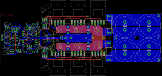
I am preparing to build this amp from boards a friend sent to me. I just want to be sure that I have the correct files. I am attaching them here. I someone would please confirm them I would greatly appreciate it. I have already built and tested the shunt boards.
Thanks, Terry
Thanks, Terry
Attachments
Hi Mihai,
Thanks for answering. My issue is that I am trying to find a schematic that has the part numbers that agree with this layout and gives the part values. The only schematic I have been able to find uses different part numbers. I have been attempting to cross reference them but worry I may get something mixed up.
One other question. The layout has a resistor in parallel with the trimmer that is not on either schematic. I have been searching through the thread but have not been able to find it.
Thanks, Terry
Putting a resistor in parallel with trimmer is a well known method used to limit the total resulting value in case of trimmer fail open. Resistor value depends on trimmer value. If you'll use 2k trimmer then resistor should be around 220ohms.
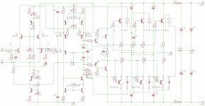
Regarding the component values, is not hard to correlate EAGLE schematics with the one attached at the beginning of this thread. The only components missing in the non EAGLE schematic are power supply capacitors (2200uF, located very closely to power BJTs and 10kuF located immediately after fuses)
Regarding the component values, is not hard to correlate EAGLE schematics with the one attached at the beginning of this thread. The only components missing in the non EAGLE schematic are power supply capacitors (2200uF, located very closely to power BJTs and 10kuF located immediately after fuses)
Give sufficient room for the smoothing capacitors.
All the medium power transistors need to be thermally connected to the heatsink.
This makes dismantleing to repair/replace very time consuming and if "dry" type insulators are used then they need to be replaced for each re-assembly.
You won't approve, but I use "sellotape" as a heatsink insulator with a splodge of thermal goop for all my initial testing. And finally replace with mica+goop for the higher temperatures that may be encountered in real listening. I have not yet had any "sellotape" failures even with some very hot power testing on the bench, but this is all very short term, hours not years.
Last edited:
Give sufficient room for the smoothing capacitors.
All the medium power transistors need to be thermally connected to the heatsink.
This makes dismantleing to repair/replace very time consuming and if "dry" type insulators are used then they need to be replaced for each re-assembly.
You won't approve, but I use "sellotape" as a heatsink insulator with a splodge of thermal goop for all my initial testing. And finally replace with mica+goop for the higher temperatures that may be encountered in real listening. I have not yet had any "sellotape" failures even with some very hot power testing on the bench, but this is all very short term, hours not years.
I'm not sure if this response is for me but if it is, I didnt design this layout. It is the the original. I am just hoping to verify the values before I start populating.
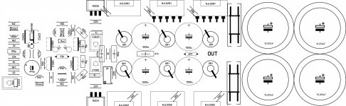
I have tried to create a silk for this amp to aid in populating it. Could you please check it and let me know if I have any errors.
Thanks, Terry
Everything looks OK to me. Go ahead and build the beast, satisfaction guaranteed
")
Hi Mihai,
because too much heat from my FC100 i decreased bias a little, from 170mA to 140 if i remember well. What is the consequnce of this bias decrease from theoretical pow ?
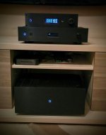
By the way since 2 yrs is my reference amplifier ! (excluding summer )
because too much heat from my FC100 i decreased bias a little, from 170mA to 140 if i remember well. What is the consequnce of this bias decrease from theoretical pow ?
By the way since 2 yrs is my reference amplifier ! (excluding summer
)Attachments
increase the Re values.Hi Mihai,
because too much heat from my FC100 i decreased bias a little, from 170mA to 140 if i remember well. What is the consequnce of this bias decrease from theoretical pow ?
By the way since 2 yrs is my reference amplifier ! (excluding summer
Try 0r15 and increase the Vre slightly, maybe from 18.5mVre to 19mVre to 20mVre
That will reduce the dissipation and maintain the optimal bias voltage.
Are you by any chance using hearing-aid device? Just asking.
Is your goal to discredit my findings before they are given? Shame on you. Have you even built any of the aforementioned amps? Just asking.
- Home
- Amplifiers
- Solid State
- RMI-FC100, a single stage audio power amplifier