How should I bias NJL diode array? I searched the thread, read it twice, and I think I saw a post somewhere before, but cannot find it anymore.
http://www.diyaudio.com/forums/solid-state/111756-rmi-fc100-single-stage-audio-power-amplifier-13.html#post1697415
Post #517
The matching was made at 100mA Ic and 20V Vce.
Why is matching done at 100mA since each output bjt is biased at 170mA according to spice sim?
From 50mA to more than 2A the hfe is practically unchanged (see the datasheet NJL0281D datasheet(4/6 Pages) ONSEMI | Complementary ThermalTrak Transistors)
The test Ic=100mA was arbitrary chosen as a good reference low value on hfe vs Ic curve.
The test Ic=100mA was arbitrary chosen as a good reference low value on hfe vs Ic curve.
From 50mA to more than 2A the hfe is practically unchanged...
Mihai, I thought the primary goal was to match the Vbe and ultimately Ic across the same type bjts, since we are not injecting each transistor with identical Ib, afaik.
The primary goal is to match the hfe across NPN and PNP AND also the Vbe among the same polarity power transistors.
One of the primary source of distortion in a class B powerstage is the hfe discrepancy between opposite polarity power transistors. The other one is caused by "the differences in the slope of the transfer characteristic near the operating point as compared with the slope at high current levels" (http://www.hpl.hp.com/hpjournal/pdfs/IssuePDFs/1971-02.pdf)
By closely matching both hfe and Vbe we will minimize the crossover distortion and by putting as many as possible closely matched BJTs in parallel, and biased at correct class B current - 26mV across one Re, we will minimize even more this distortion.
Last edited:
26mv is the theoretical total voltage dropped over internal and external emitter resistors. We do not know exactly the value of internal emitter resistor but we can detect the minimal distortion point variating the bias current.
I have found that minimal crossover distortion, in the particular case of 0.1ohm external Re, is attained at roughly 18-19mV voltage doped over external Re. Higher values will increase the distortion but is not so worse to err on that direction rather than in the other, less than 18mV
I have found that minimal crossover distortion, in the particular case of 0.1ohm external Re, is attained at roughly 18-19mV voltage doped over external Re. Higher values will increase the distortion but is not so worse to err on that direction rather than in the other, less than 18mV
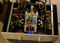
Well, I am done now. I just have one little problem - how do I stop those little hairs on the back of my neck from standing up while this baby is playing? 
I am done with amps now, I might build one day another just like this one. I just need to solve some minor hum issues, and it's getting a bit hot with Re=0.1 on those small sinks, so I might go for 0.22.
I am using BF862 in the front. Right channel pair is matched on Idss only at 0.01mA, and offset is at 0.4mV. The other channel is a bit loose at 1.4mV.
Attachments
I had a strange occurence today. I had to increase all Res to 0.15ohm since my sinks were not up to the task. When I reassembled the amp, I got trafo hum from both channels - and excessive buzzing noise from the output stage toroid itself. I disconnected output stages of both channels and noise went away. I connected one channel back, still no noise. I put back the second channel - again no noise! Any ideas what happened?
And what happen is you plug in first the faulty amplifier?
Is the DC level at the output of the amplifier 0V?
Toroid may buzz when a DC current flew through their windings. Depending on the way you designed the power supply (one diode bridge or two diode bridges?), different consumption on + and - rail main lead to DC current.
Check DC condition with no signal and compare Left and right channels.
30+30Vac would be good to use with 8ohms speaker.
150VA would power one channel.
But, be careful, some devices dissipate a lot more power when the higher voltage transformer is used. You really do need to check every component for current flow to ensure the circuit will still work as designed and then check every component for maximum power dissipation to ensure they are all within a sensible operating temperature.
If you cannot do this your self, then you should not be changing the transformer from the designer's specification !!!!!!!!!!!!
- Home
- Amplifiers
- Solid State
- RMI-FC100, a single stage audio power amplifier