I think the problem is one of this:
-Q21 and Q18 with too little beta (fake ones)
-Fets short-circuited
-Wrong value of R29
-R25 not connected
-Zero Volt of the simmetrical PS not connected.
If all things go OK, I guess is expected about 10V VDS in the fets.
Cheers,
Marcos
-Q21 and Q18 with too little beta (fake ones)
-Fets short-circuited
-Wrong value of R29
-R25 not connected
-Zero Volt of the simmetrical PS not connected.
If all things go OK, I guess is expected about 10V VDS in the fets.
Cheers,
Marcos
the jFETs were Idss=10.2mA before installing and still measure 10.2mA after removing.roender said:Did you measure the Idss for k170 used? What values did you found?
I will try the tracking the pair over a range of Id to see if they still match each other. I have another 10.5mA matched pair but they are reserved for the second board.
Zero Volt of the PSU not connected!m2003br said:I think the problem is one of this:
-Q21 and Q18 with too little beta (fake ones)
-Fets short-circuited
-Wrong value of R29
-R25 not connected
-Zero Volt of the simmetrical PS not connected.
If all things go OK, I guess is expected about 10V VDS in the fets.
Cheers,
Marcos
Is that why I see between 280mVdc and 550mVdc across R26 the 22k Zin resistor?
Could the jFETs be self biasing to minimise power across their junctions and pulling their source voltages high rather than locked into Zero Volts.
Q8 is the same batch as Q18/21. It seems to work OK.
R29=9k96
R25 in place.
Only God knows what happen in a circuit intended to have a zero volt reference, without that...
In this case, some reverse polarisation D-G or S-G, because N fets DO circulate current in the gate, if positive in respect to lowest potential electrode, no matter if D ou S. JFets are reversible (D-S) by your own nature...
Marcos
In this case, some reverse polarisation D-G or S-G, because N fets DO circulate current in the gate, if positive in respect to lowest potential electrode, no matter if D ou S. JFets are reversible (D-S) by your own nature...
Marcos
Success.
Thanks for all the suggestions.
The front end works with the Zero Volt reference from the lab PSU Zero Volts to the main PCB ground and then through that 10r to tie the jFETs Sources to near zero volts.
The question becomes: Where do we connect the Low Current regulated PSU? Which end of the 10r gets the reg return?
BTW,
I soldered the old matched pair back in.
If the output from your regulated front end PSU is really clean, then would the reg ground be better attached to the signal ground?
The front end sends almost zero current to the front end Zero Volts connection. What influence would this have on the cleanness of the signal ground?
Missing out the Zero Volts connection shows that the front end is susceptible to noise voltage on the signal ground since the source voltage of the FETs is intimately tied to this.
Or is this back to front logic?
GB Onsemi NJL 0281 / 0302
Hi all,
trying to set up Group Buy for NJL0281/0302.
Please have a look here:
http://www.diyaudio.com/forums/showthread.php?postid=1745010#post1745010
Cheers Ernst
Hi all,
trying to set up Group Buy for NJL0281/0302.
Please have a look here:
http://www.diyaudio.com/forums/showthread.php?postid=1745010#post1745010
Cheers Ernst
Last week i bring my RMI-FC100 at my local HIFI dealer (the owner is an old friend) to make some listening sessions. I am willing to change my speakers , but i was curious to do my choice with my little home made amp, just to see if it can reveal the subtilities of differrent speakers models of the same brand.
So i lhave two B&W speakers model already pre selected :
- 703 (http://www.bowers-wilkins.co.uk/display.aspx?infid=1098&sc=hf)
and the higher range model 804 (http://www.bowers-wilkins.co.uk/display.aspx?infid=1154&sc=hf ).
After several hours of listening, i was shure enough to pay the extra cost for the bigger one. The guys present was surprised with the result. I was very pleased how it perform , smooth treebles , tight bass, superb medium not colorised, the details , soundstage ect. We did not compare the amp directly with the others , but theses guys are selling Classé Audio , McIntosh, Marrantz referrence serie, Arcam, etc.
Their verdict is a : Very tight amp, not in the smooth or in the harsh side, simply neutral. They proposed a smooth source for the best result with theses speakers.
Go with it, guys.
Attachments
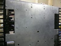
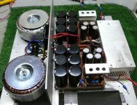
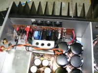
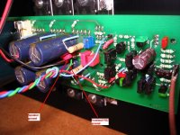
DRZ1 said:main board with the soft start
Denis,
Nice work, keep going!
How big are your transformers - more than 200VA? It is really necessary a soft start circuit?
Cheers,
Mihai
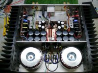
240 VA each.
I think it's more the filtration than the transfo capacity that determine the need for a soft start.
with 60,000uF per side i think thats better with a soft start. But mine is simplest as possible, 100 ohm in series with the two primaries (115V) and when the supply reach 70% of nominal value, the relay short the resistors.
With this set up i dont have this famous HUMMMMMmmmmm at the power on.
well done.DRZ1 said:With this set up I don't have this famous HUMMMMMmmmmm at the power on.
I suspect you also gain the advantage of using a relatively low value of mains' fuse.
Two gains from one simple add on.
I wish more would think about what they ask of mains' equipment.
- Home
- Amplifiers
- Solid State
- RMI-FC100, a single stage audio power amplifier