So now it is 820/12.7K. It will go a way lot more loud than I want to hear it, but it has always been like that. Given the change this change has made, I'm temped to try it with about 1.2K/12.7, I'm thinking it would be even finer to finesse the volume. But I am gathering all of my acorns together to build 4.1b because evidently I do not have the best possible adjustability. Some of the stuff I bought to build 4.1b way back, got pirated in other projects, I just have to regather the BOM.
How important is the DC offset spec? The two pcb's had drifted over the last four years: on was at 15mV, the other was I think 61. I had sent them when building the prototype and I think you were telling 50mV once the circuitry is warmed. Today I just sent them at 25mV, should I crank them up to 50mV?
How important is the DC offset spec? The two pcb's had drifted over the last four years: on was at 15mV, the other was I think 61. I had sent them when building the prototype and I think you were telling 50mV once the circuitry is warmed. Today I just sent them at 25mV, should I crank them up to 50mV?
The normal listening position is 9-10 o'clock, with 11 o'clock being about as loud as you ever want to push it. So, you want to adjust the gain to match the headphone sensitivity such that the loudness is in that ballpark.
Never adjust the gain based on what the output is with the volume turned all the way up.
The DC offset should be less than 100 mV, and trimmed to get a minimum value when the circuit is warmed up. The exact value is not important, it should just be reasonably low.
Never adjust the gain based on what the output is with the volume turned all the way up.
The DC offset should be less than 100 mV, and trimmed to get a minimum value when the circuit is warmed up. The exact value is not important, it should just be reasonably low.
My 4.1b boards have been running for more than three weeks now. I used Mundorf MCap ZN for C1 in this build, and I was not too surprised to hear those new caps sound very dark for the first few minutes and then open up. Now I don't think I could tell you if there is any different from the ClarityCaps I've used for years in 4.0.
I built them open according to the BOM.
I'm curious about 4.2b with its larger caps - and I've seen one build with a kluged large cap in place of the 4.1B 2x1000uF caps. Have you noticed any difference in SQ between the two versions?
I built them open according to the BOM.
I'm curious about 4.2b with its larger caps - and I've seen one build with a kluged large cap in place of the 4.1B 2x1000uF caps. Have you noticed any difference in SQ between the two versions?
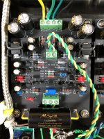
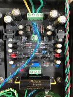
Attachments
I don't think anyone has done an A/B comparison, but I wouldn't sweat it. The 4.2 revision was to allow the use of larger caps when building the high current varents of the circuit. I switched the BOM over from 1000/100 caps to 3300/330 caps "just because" but note that although the individual values are larger there are fewer of them, so I really don't expect anything to change much. Some people have advanced the idea that big parallel arrays of small value caps sound better than single large cans, but I don't subscribe to that and anyway, the difference between 1x3300 and 2x1000 is either way marginal.
Add regulators for each channel like (LT3042/5 - LT3093/4) on the Z-Reg output to the amplifier, is that a bad idea? why? or unnecessary?I don't think anyone has done an A/B comparison, but I wouldn't sweat it. The 4.2 revision was to allow the use of larger caps when building the high current varents of the circuit. I switched the BOM over from 1000/100 caps to 3300/330 caps "just because" but note that although the individual values are larger there are fewer of them, so I really don't expect anything to change much. Some people have advanced the idea that big parallel arrays of small value caps sound better than single large cans, but I don't subscribe to that and anyway, the difference between 1x3300 and 2x1000 is either way marginal.
Three terminal fixed or adjustable regulator ICs do not sound good, in my opinion. Although some people (mostly the Japanese set) have expressed a preference for unregulated rails, like for a power amp, residual background hum is a lot easier to hear with a headphone amp and it's pretty near impossible to remove it by passive means. I find the Zener + pass transistor a useful middle ground. Cuts the hum but still sounds lively and dynamic.
I'm planning to building the Sapphire 4 but bit of a noob when it comes to electronics and hit a little roadblock. So i planned using the X-reg board and was wondering if Q15 and Q16 are necessary along with the zener's and 4 resistors if rectified 12V is coming in? Thx in advance.
EDIT: And i was wondering how big of a transformer i really need because the xreg cannot do more than 150ma.
EDIT: And i was wondering how big of a transformer i really need because the xreg cannot do more than 150ma.
Last edited:
Hi, please don't use the X-reg with the Sapphire. Stick to the Z-reg which is built into the Sapphire boards.
Even if the current output was supported, there is no need to apply intense voltage regulation/filtering to the Sapphire's supply rails due to the excellent PSRR inherent to the diamond-buffer based input stage.
Even if the current output was supported, there is no need to apply intense voltage regulation/filtering to the Sapphire's supply rails due to the excellent PSRR inherent to the diamond-buffer based input stage.
Re. active ground: don't do this. It serves no useful purpose and just increases the output noise.
Re. transformer, the resistances will all have to change, the zener diode replaced with 18 V types, the capacitors replaced with 35 V types, and the power is still wasted since you'll never take advantage of the additional voltage headroom anyway.
Re. transformer, the resistances will all have to change, the zener diode replaced with 18 V types, the capacitors replaced with 35 V types, and the power is still wasted since you'll never take advantage of the additional voltage headroom anyway.
Hey,
I´ve used the search function, but cant find any infos to my issue...
So I build 2 boards of sapphire, one of them works fine, bias after heading up close to zero v.
The second one is a little more trouble:
V-- -13-13,5v
V++ 13-13,5v
V+ 11,29v (measured at c10)
V- 9,21v (measured at c11)
Output bias: around 4v
Regarding to your earlier remarks I matched the zener-diodes (BZX 79-C12 NXP)
After my first measurements I reflowed the solder joints in the power section.
So the mistake appears to be in the power supply section, because the V+/V- are not symmetrical?
Any clue where to search? I´m going to investigate further tomorrow...
Any hints or tips are welcome")
I´ve used the search function, but cant find any infos to my issue...
So I build 2 boards of sapphire, one of them works fine, bias after heading up close to zero v.
The second one is a little more trouble:
V-- -13-13,5v
V++ 13-13,5v
V+ 11,29v (measured at c10)
V- 9,21v (measured at c11)
Output bias: around 4v
Regarding to your earlier remarks I matched the zener-diodes (BZX 79-C12 NXP)
After my first measurements I reflowed the solder joints in the power section.
So the mistake appears to be in the power supply section, because the V+/V- are not symmetrical?
Any clue where to search? I´m going to investigate further tomorrow...
Any hints or tips are welcome
since I cant edit my posts, mistakes found:
1) was a wrong r6 (some wrong value found its way into the 5k bag)
--> Probably my own fault
2) after checking all resistors code, transistor legs etc. I found one of the capacitors to be soldered in wrong polarity
--> definitely my own fault
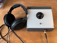
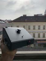
Now back to putting this into an enclosure and I will be back once everything is done!)
1) was a wrong r6 (some wrong value found its way into the 5k bag)
--> Probably my own fault
2) after checking all resistors code, transistor legs etc. I found one of the capacitors to be soldered in wrong polarity
--> definitely my own fault
Now back to putting this into an enclosure and I will be back once everything is done!
)
After a long time.
I still use my Sapphire almost daily, it's connected to my computer and the ASUS Xonar STX soundcard.
I bought a Ayre QB-8 Twenty USB DAC, and I have that connected to a TEAC HA-501.
Use both with HD-600 headphones.
So... I got to thinking.
The reason I don't use the Sapphire with the Ayre is that the DAC's balanced outputs sound way better than its single ended output signal, and the TEAC has XLR inputs... the Sapphire does not. The combo sounds fantastic, but the TEAC is very slightly soft/polite/light. It would be nice to have the balanced sound of the Ayre into the more lively, energetic-sounding Sapphire. To do that I need to add XLR inputs.
There are a few options. One is to buy a 4 gang volume control and use 4 Sapphire boards, balanced in balanced out. The other, more sensible approach is to add a Bal-SE converter circuit board as a mod to the Sapphire chassis. While I'm here, I know a number of you were interested in running the Sapphire with balanced outputs so a SE-Bal converter would also be something I'm putting on the to-do list.
Suggestions?
- Home
- Amplifiers
- Headphone Systems
- RJM Audio Sapphire Desktop Headphone Amplifier