Damn, that sucks.
Seems like the trimmer is just out of range. What is your value of R6 and what is the exact voltage of V+ and V- for both boards? The positive and negative supply should be within 200 mV of each other.
R6 = 2k can trim the input DC voltage over 1% of the 22 V V+ V- combined rails, i.e. 220 mV. For 27 dB gain it should be able to move the output through a range of just under 5 V.
The quick and dirty solution is to move to a 5k trimmer. If the Zeners aren't giving you equal V+ and V- rails to power the amp, you can replace a outlier Zener. That's what worked for me. Otherwise you have to look at why your carefully matched transistors are giving such a comparatively large offset in one channel only.
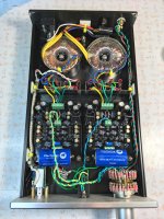
Took the board out, re-flowed all my solder joints, paying special attention to some of the thick ones (you warned us of the ground plane) that were slow to heat when I did first assembly, looked at positions of everything, all transistors are right side up. Can't see any problems. Poking around, comparing voltages from one board to the other, finding no anomalies except the trimmer.
I checked V+ and V-, board to board, and they seem right. I should have written down the values - but they were both the same. I'm wondering if I have a bad capacitor. Since I had to take Sapphire 2 apart for the heat sinks, I used the 1000 uF caps from them (I tested them all, they seemed fine).
R6 is 2K. It does seem like, if I had more range, I could zero it out. But I installed what I ordered from the BOM. The left channel is behaving perfectly, though I think I'm near the limit of the trimmer. I'm tempted to put Sapphire 3, right channel, in, ha.
Left channel, the good one: V++ is 18.87, V-- is 18.9
After several minutes, V+ is 10.83, V- is 10.75
Right channel: V++ is 18.91, V-- is 18.92
After several minutes V+ is 10.8, V- is 11.09
This is telling me the capacitors are OK. Do I need to try changing the Zeners?
After several minutes, V+ is 10.83, V- is 10.75
Right channel: V++ is 18.91, V-- is 18.92
After several minutes V+ is 10.8, V- is 11.09
This is telling me the capacitors are OK. Do I need to try changing the Zeners?
Last edited:
The power supply voltages aren't the problem, so it must be the transistors.
The most obvious thing that would cause excess offset is mismatched hfe between Q1,2, meaning the current flowing out of the base of Q1 and into the base of Q2 are not equal. The excess or deficiency is drained out / sourced up through R4,5,6 creating an DC input offset voltage.
Two tentative solutions. One is to replace Q1,2 with a more closely matched pair. The other is more sneaky ... if you have more 100 kohm resistors you can solder another one across R4,5 on both boards. (on the bottom, using the leads of the existing resistor is probably cleanest) So now the resistance halves to 50k. This will mean the current missmatch can only generate half the voltage it did before, and it also means your trim R6 has double the range, total 4x more power to being the offset under control. You can also replace the resistors with 47k, same net effect.
The no-free-lunch downside is the input impedance of the amp seen by the volume control output drops from 50k to 25k. If you are using a 25k pot fine, if 50k that's probably not a long term option though it should get you up and running.
Last edited:
My BC337's were all in the 250 to 270 HFE range, no outliers. In my 100 BC327's I had none with HFE values between 220 and 280. So Q1 and Q2 are certainly not matched.
Furthermore, of my BC337's I had only one with an HFE of 280! The rest were all higher values.
Wait - Q1 and Q2 are miss-matched on the left channel, too. Yet it trims out.
Furthermore, of my BC337's I had only one with an HFE of 280! The rest were all higher values.
Wait - Q1 and Q2 are miss-matched on the left channel, too. Yet it trims out.
Last edited:
Mine aren't matched to the same hfe either, they were in the range of 220 for the npn and 250 for the pnp. Something of that order.
There is a certain amount of luck involved I guess, as other transistors, the zeners, all influence the offset slightly, so two outliers can balance out at the end, ... or not as the case may be. Of the 5 V trim range you find yourself within 1.7 V of zero, so it's not so far off. Doubling the trim adjustment range would have covered it.
The problem with making the trim pot value larger is it becomes harder to make the fine adjustment to get he output under 50 mV.
My recommendation still stands: try different set of transistors for Q1,2 or half the value of R4,5. Last resort is use 5k for R6.
o wait, another idea if you have some spare resistors: adjust R4 or R5 to make R4 slightly smaller or R5 slightly larger than 100k, this has the effect of moving the trim adjustment range up to higher voltages to such that it will eventually include zero. Making R5 101k (100k+1k series) should do it.
Last edited:
The fault is on me - I underestimated the variation that would be found in the wild and R6 is lower than it should be. After fixing my Zener diode I could center mine with just R6 = 1k, though I thought 2k should be enough to cover most eventualtities. 5k would have been the right choice, clearly.
It's odd, since you really did go the extra mile on this, but remember we are talking a 1% difference here. It wouldn't take much - maybe the transistor properties changed when it was soldered. It's within the bounds of possibility.
Either replace transistors or trim R4,5 manually to rebalance the range of the trim pot R6, or reduce R4,5 to ~50k.
I ran through the numbers, to check what kind of hfe mismatch would cause what level of output offset.
For a hfe Q1 200,Q2 300, (100 difference) gain 27 dB, R4,5 100k and R7,8 10k, the uncorrected output offset would be 2 V, falling within the +/- 2.5 V trim range of 2k R6. So anything less than 100 difference should be able to be trimmed right out with the 2k trimmer without any problem.
For the absolute worse case of 160 and 400, the offset would be just under 5 V, which would require R6 of 5k to trim out as it provides +/- 6 V trim range.
In your case having offset 1.7 V remaining after trimming with R6=2k (max 2.5 V in one direction) means the uncorrected offset was 4.2 V, close to the worst case hfe pairing.
From your previous report on matching, I understand all your BC337 were 250-270, and you had plenty of BC327 in the 290-300 bin to use against them, giving a maximum mismatch of only 50. That's as good as I had, and should be able to be trimmed effectively with only 1k R6. (my experience and also my calculation.)
I conclude that at least one of Q1 Q2 on the bad board is not operating with the hfe value you measured. There are other possibilities, but all of them are relatively unlikely so I'd say replacing the input transistors would be the first step.
Attachments
Last edited:
Been clearing snow, picking up my wife at the airport, etc. today. -21C, 25 cm of white stuff here, what's Kyoto like?
I'm suspecting a bad transistor in the mix, but here's another "duh" moment. For the PNP transistors, I chose the highest HFE bin of which I had enough; 320. I don't know what I was thinking, I should have used the 290 bin, I had enough of those (and one at 280, but none between 220 and 280). The NPN transistors, while they ranged from 255 to 270, most fell into 255-260, so that's what they are in the circuits. That's a difference of 60. By switching in the 290 lot, the difference will fall to 30. If I can find an NPN with an HFE of 270, that shave it down to 20.
A mountain guide I know characterized pleasurable activity as something that's "fun even when it isn't fun". I'm still there, even though my right channel isn't working yet. It will, soon.
I sent Mouser a note and asked them if there is something irregular about their stock of BC32725.
Last edited:
It snowed briefly this morning. Second or third time this year. Nothing on the ground though, and the plum blossoms are already starting in more sheltered spots.
Your offset is negative, as expected for Q1 hfe high and Q2 hfe low so it seems we are on the right track here, even though the magnitude is way off: As I noted above, a difference of ~60 should have been no problem at all to trim off. I suspect Q2 got zapped. However, since you are out to replace them anyway might as well find a pair as close as you can. The lower the trim imbalance required the better the circuit is going to perform.
Your offset is negative, as expected for Q1 hfe high and Q2 hfe low so it seems we are on the right track here, even though the magnitude is way off: As I noted above, a difference of ~60 should have been no problem at all to trim off. I suspect Q2 got zapped. However, since you are out to replace them anyway might as well find a pair as close as you can. The lower the trim imbalance required the better the circuit is going to perform.
Yes, Fairchild parts from Mouser. I'm surprised, too. Maybe I should tell them.
Just because you purchased Fairchilds from Mouser really doesn't mean that much other than they're probably not fakes.
Like more and more things in today's world, I'm beginning to believe a lot of transistors of late are being manufactured in the same Chinese facility(s) and rebranded/relabeled.
Of course this is just my opinion, but I don't think you see the consistency in components you saw years ago.
Not enough improvement with the transistors I have
I changed Q1, 3, 5, 7, 9, 11 for lower HFE values, and changed Q2 for a slightly higher HFE. I tested Q2 that I removed and it had an HFE of 257; the replacement is 272, highest value I could find in the lot. Now my leftover voltage is down to -1.3. An improvement, but not enough!
I have some Bournes 5K trimmers but the pinout is wrong - I think they're 3299's. Staggered pinout, rather than inline. My volume pot is 50K. Before I start changing resistors, I'm going to see if I can get a 5K inline trimmer tomorrow, B&E Electronic supply stocks some.
Seems it wasn't the transistors then. Could you remeasure R4 and R5? Doesn't matter what they are so much as to confirm they are the same.
The quickest fix now is to pop out one lead of R5 from the board, and solder a 1k resistor between the flying lead and the pad, so that R5 becomes 101k effectively. That should bump up the centerpoint voltage of R6 by 110 mV, moving the trim output range from -6.1~-1.7 to -3.6~+2.9 V.
The quickest fix now is to pop out one lead of R5 from the board, and solder a 1k resistor between the flying lead and the pad, so that R5 becomes 101k effectively. That should bump up the centerpoint voltage of R6 by 110 mV, moving the trim output range from -6.1~-1.7 to -3.6~+2.9 V.
Last edited:
- Home
- Amplifiers
- Headphone Systems
- RJM Audio Sapphire Desktop Headphone Amplifier