Bibio
To get a better understanding maybe build a cmoy amp with one of your opamps. Go to Wikipedia and read up on "voltage divider" as it will help you to understand the two feedback resistors job. Also check opamp datasheets for the gain equations. The voltage divider and gain equations are important and pretty simple. For cmoy circuit find equivalent resistance of the two feedback resistors in parallel and make input resistor equal to that value. It helps cut down offset and I'm not sure what else you do that for. Anyway its a good learning circuit that covers the basics. You'll learn a lot in a short time.
I find diyaudioprojects.com to be amazing for learning. Especially their projects section. They document several builds and give detailed explanations of things most folks here take for granted.
Last edited:
let see if i have this right for a LPF
47r + 0.1uf (X7R) = 33khz cutoff ?
i place the 47r on the hot output and then place the 0.1uf between the hot and cold after the resistor?
Yes. However, an X7R cap will vary it's value as the temperature changes. For the audio path, use a COG/NPO or polypropylene, or PPS SMT cap.
And TI recommends a -3dB point of 153KHz - 470 ohms with a 2.2.nF (2200pF) for the PCM150X DACs.
In JG's filter, he used a 4.7nF (4700pF) due to the DAC they used as well as the coil which was a secondary filter, and finally an RF filter of 470 ohm with a 150pF cap to ground.
My understanding is that the main task here is to provide equipotential plane to every board (which is somewhat naive concept anyway), conveniently labeled GND/COMM/whatever, and that every conductor has some impedance. Then any current from point a to point b develops voltage difference. To reduce that effect you can: 1) reduce current 2) reduce conductor impedance.
1) can be achieved using opamp with very high input impedance (this would explain jfet vs bjt anomaly in my case).
I presume your advice relates to 2), that somehow using star ground scheme with direct 10R connection to chassis would do the trick. but chassis is/must/ought be connected to PE. Using PE for return currents is not elegant at best. Besides increases overall inductance, which is not a good idea, I guess, when you have Rpi board with its switching regulators nearby. so this concept is unclear to me.
Forta, you're speaking way over my pay grade!
")
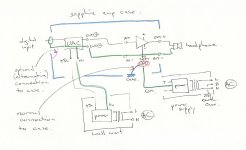
From my simplistic perspective, audio ground and secondary power ground are defined by the Sapphire's design - the GND on each board is a star point for power and audio. Both are isolated from primary power ground by the power transformer.
If one adds a RPi (or anything else) that does not get power from the power supplies on the Sapphire boards, then there are two paths to primary power ground. Attaching the audio grounds together creates a loop because because of the impedance difference of the grounds due to the power supplies having different 0V references.
The better way, in my opinion, to set something like this up is to remove the power supplies from the Sapphire and make a common power supply where all voltages can be defined from. That power supply then provides a common ground point for all modules in the box.
Even with multiple power supplies in a box or in an external box, all the power supplies have a common ground point for reference - the output of all the power supplies common. An example is the Group DIY 51X, where +/-16.5V, +/-24V, and +48V all reference the same ground. In addition they also pass chassis ground as a separate wire run. That allows for both referencing chassis ground, lifting off power ground, referencing power ground and allowing audio ground to be tied direct or via a lift (10 ohms).
Last edited:
In JG's filter, he used a 4.7nF (4700pF) due to the DAC they used as well as the coil which was a secondary filter, and finally an RF filter of 470 ohm with a 150pF cap to ground.
i never read the whole tread yet. to me the above sounds very much like a speaker xover which i dont understand fully either... lol
BTW the IQaudIO DAC+ uses a headphone amp chip as its main output with a supposed variable 2v on the analogue side as a HW volume control. if that makes a difference.
let see if i have this right for a LPF
47r + 0.1uf (X7R) = 33khz cutoff ?
i place the 47r on the hot output and then place the 0.1uf between the hot and cold after the resistor?
I bet you do have LPF on your DAC board already. Why would you need another one?
Forta, you're speaking way over my pay grade!
Yeah, nice joke. I know next to nothing about circuitry.
Even with multiple power supplies in a box or in an external box, all the power supplies have a common ground point for reference - the output of all the power supplies common.
I have no problem with that. I've got some doubts when chassis is used as a part of audio circuit, rather than for safety purposes only. And wonder why my box sounds so damn good, when it should have scored miserably.
IQaudIO DAC+ headphone amp chip looks like he is using TPA6130A as it has volume control
IQaudIO DAC+ DAC chipl
so from the blurb it looks like there is no need for DC output blocking which if i'm right there is no need for DC input blocking on the Sapphire which would remove the need for C1. what i dont understand is what the k ohm size is (volume pot K) on the output of the DAC+ that the Sapphire input 'sees'.
If one adds a RPi (or anything else) that does not get power from the power supplies on the Sapphire boards, then there are two paths to primary power ground. Attaching the audio grounds together creates a loop because because of the impedance difference of the grounds due to the power supplies having different 0V references.
The power supplies don't have different 0 V references, they are tied together by the signal ground (the wire from OUT- of DAC to IN- of Sapphire amp). As long as no current flows along signal ground, they are at the same potential by definition. If large power supply currents are allowed to flow through the signal ground this will induce hum and noise in proportion to the induced voltage (I*R) where R is the resistance of the signal ground. Since the power supplies are independent, however, there is no reason why return currents for the Sapphire supply should flow to the DAC power supply for example. They operate independent from each other.
There are concerns. One is that noise from the 5V power supply is coupled into the analog signal somehow. The other is that the case connection was somehow connected to a "dirty" ground (relative to the input signal ground) so that the case itself induces noise into the input.
Attachments
Last edited:
100pf compensation caps
The 100pf compensation caps, C2 and C3, are they present for stability, or do they provide Miller compensation (as in a blameless VAS stage), or both?
If they do provide increasing local feedback with increasing frequency, at what frequency does the localization start? Is it within the audio spectrum? And if so, how is that frequency calculated? Just a simple
F = 1 / (2 * PI * R * C), approx value of R, etc., etc...
I'd be grateful for the 30,000 foot overview.
IQaudIO DAC+ headphone amp chip looks like he is using TPA6130A as it has volume control
IQaudIO DAC+ DAC chipl
Volume control is digital, handled by alsa; control codes sent via i2c to pcm5122. Look at the source code of kernel modules used by pidac+.
Since the power supplies are independent, however, there is no reason why return currents for the Sapphire supply should flow to the DAC power supply for example. They operate independent from each other.
You meant KCL/KVL doesn't apply here?
You meant KCL/KVL doesn't apply here?
Please elaborate.
- Home
- Amplifiers
- Headphone Systems
- RJM Audio Sapphire Desktop Headphone Amplifier