Since I didn´t want to hijack Chops´ thread http://www.diyaudio.com/forums/showthread.php?s=&postid=566960#post566960 any longer, I have started this new one with some more information about ripoles – the smallest way to build dipole (sub)woofers. For all of you who didn´t watch the discussion from the start, please read posts #358-376 in the thread above. Otherwise you might not have the proper background to get what this is all about.
I have promised to share with you some more insight into this special kind of dipole (sub)woofer and here we go. Don´t blame me for being long-winded - some of you have asked for it. Since I haven´t found out yet how to squeeze 2 pictures into one posting this info will be divided into 5 postings.
All pictures and diagrams I show are protected by copyright laws. Most of them have been published in the WWW before, but I haven´t asked permission to show them here. So be prepared that I might take those pictures off the forum after some time.
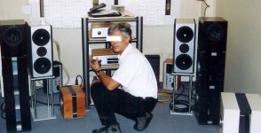
Let me first introduce you to Axel Ridtahler, the inventor of the ripole (sic!) principle. In the picture you should find 6 ripoles (each as two N ripoles with a common front opening in push-push configuration. He calls it BMC configuration). I believe the ripole in the front right corner with a 16” driver is the one to talk about in my next post.
To be continued …
I have promised to share with you some more insight into this special kind of dipole (sub)woofer and here we go. Don´t blame me for being long-winded - some of you have asked for it. Since I haven´t found out yet how to squeeze 2 pictures into one posting this info will be divided into 5 postings.
All pictures and diagrams I show are protected by copyright laws. Most of them have been published in the WWW before, but I haven´t asked permission to show them here. So be prepared that I might take those pictures off the forum after some time.
Let me first introduce you to Axel Ridtahler, the inventor of the ripole (sic!) principle. In the picture you should find 6 ripoles (each as two N ripoles with a common front opening in push-push configuration. He calls it BMC configuration). I believe the ripole in the front right corner with a 16” driver is the one to talk about in my next post.
To be continued …
Attachments
Ripoles - Honey, I shrunk the dipoles! #2
The picture shows a simulation of a 16” driver in a BMC ripole. Measurements of another driver in the next post will show, that SPL below 50 Hz is too optimistic, but otherwise the simulation seems to be quite correct. I include this picture because it’s the only polar diagram of a BMC ripole I know of. The dipole 8 is somewhat compromised. SPL in the polar plot is the same as in the left diagram (not as shown on the diagrams x-axis). So attenuation is ~12dB at 90°-120°.
The picture shows a simulation of a 16” driver in a BMC ripole. Measurements of another driver in the next post will show, that SPL below 50 Hz is too optimistic, but otherwise the simulation seems to be quite correct. I include this picture because it’s the only polar diagram of a BMC ripole I know of. The dipole 8 is somewhat compromised. SPL in the polar plot is the same as in the left diagram (not as shown on the diagrams x-axis). So attenuation is ~12dB at 90°-120°.
Attachments
Ripoles - Honey, I shrunk the dipoles! #3
This is the measurement of a Vifa 30 WN 380 RL/8 woofer in a N ripole. Mic distance 1m. Black line is without any compensation, dotted line is with a zobel/notch compensation I will explain in the next post. Dotted line at the left is for some active x-over which I don´t discuss here.
Note that with the compensation SPL is flat from ~300Hz to 50 Hz. If you are lucky room gain will take care from there on. So you don´t need any special equalisation.
The cabinet for this ripole is 9” wide, 16” high and 14.5” deep.
Attachments
Ripoles - Honey, I shrunk the dipoles! #4
Ridtahler recommends a line impedance and a notch filter to tame the resonance peak and flatten the SPL response of the ripole. L1 should be 6.8mH for a 8 Ohm driver (3.4mH for 4 Ohm). Value isn´t critical. Anything between 5 and 9mH will do. Resistance of L1 need not be very low since a higher resistance (0.6-0.8Ohm) would help to raise Qts.
Values for the notch filter are R1=2.7 Ohm (including the coil resistance of L2), C1= 47µF, L2= 6.8mH. These values are for the configuration of post #3, but since the resonance peak depends on the ripole cabinet, it should be a good guess for any 12” driver to start from.
Attachments
Ripoles - Honey, I shrunk the dipoles! #5
Last diagram is a comparison between a U dipole (Kreskovskys NaO-Woofer, black line) and a ripole (dotted line). These are in room measurements with a mic distance of 4.5m from the dipoles. So room resonances are dominant. There is no compensation or equalisation. While most people would prefer the black line - two considerations:
(1) The ripole roll off below 130 Hz seems to be less steep than the U frame roll off. So it should be easier to equalise.
(2) The volume of the ripole is half the volume of the U frame!
Drivers are identical (GBS-512/4 with a less than perfect Qts of 0,56).
That´s all I can tell you about ripoles. Have fun.
Rudolf
Attachments
Hi Rudolf
Thanks for your information.
Some questions -
Post 2 - the simulation of a 16” driver in a BMC ripole:
- When these are not boxes, do you know why they refer to 72 litres – is that notional volume of the exterior measurements?
- In the left graph, what are the blue and black curves?
Post 3 – you said “flat from ~300Hz to 50 Hz. If you are lucky room gain will take care from there on”.
IIRC, dipoles do not ‘receive’ room gain.
What issue of Hobby HiFi was the article in?
And who could translate it into English?
Cheers
Richard
Post 2 - Most likely, and it seems that the blue line is the response with crossover.rick57 said:Hi Rudolf
Thanks for your information.
Some questions -
Post 2 - the simulation of a 16” driver in a BMC ripole:
- When these are not boxes, do you know why they refer to 72 litres – is that notional volume of the exterior measurements?
- In the left graph, what are the blue and black curves?
Post 3 – you said “flat from ~300Hz to 50 Hz. If you are lucky room gain will take care from there on”.
IIRC, dipoles do not ‘receive’ room gain.
What issue of Hobby HiFi was the article in?
And who could translate it into English?
Cheers
Richard
Post 3 - I believe that is true.
Using the air mass seems to take away one of the main advantages that a dipole has - transient response! It is, I believe, as good as the design of the driver allows, in theory the best you can get for a given driver. It is a very small air mass and would restrict driver movement, which would seem to increase power handling, but this would surely reduce output at the same time, hence requiring more power.
I'm not trying to shoot down the idea, just get my head around it.
For a moderate output high fidelity music system, it does have appeal - make them the same size as a stand for bookshelf speakers.
I'm not trying to shoot down the idea, just get my head around it.
For a moderate output high fidelity music system, it does have appeal - make them the same size as a stand for bookshelf speakers.
Hello Rick,rick57 said:When these are not boxes, do you know why they refer to 72 litres – is that notional volume of the exterior measurements?
- In the left graph, what are the blue and black curves?
Post 3 – If you are lucky room gain will take care from there on”.
IIRC, dipoles do not ‘receive’ room gain.
I can´t tell whether those 72 l are interior or exterior. There are no dimensions of the ripole given.
The black line is without correction, the blue line with a passive correction filter. This filter would be more complex than the one described above.
Regarding room gain: I´m not really shure about that, but I believe room reaction is independent from the exciting source. Monopole and dipole excite the same resonance frequencies, but - depending on there location in room - to different degrees. What I do know: With dipoles I get that strange omnidirectional "pressure" feeling of very low organ notes in my room too.
What issue of Hobby HiFi was the article in?
The first one in issue 3/2002, the comparison between different types of dipoles in 2/2005.
And who could translate it into English?
I´m not THAT fluent in English to do the whole bunch for you. But you may try babelfish and ask me, where the translation doesn´t make sense to you.
Rudolf
Room gain - I haven't seen actual measurements which indicate either way, but you can simulate the room response of a dipole (showing only the impact of the room), and those sims that I have done show that room gain isn't happening.
Attached file shows a comparison of the room response different subwoofer options in my listening room (4 x 5m x 3m ceiling).
Note how where there is room gain for the monopoles, the dipole has an inverse gain ie a loss over and above the dipole rolloff.
Perhaps someone can give a theoretical reason for this, or conversely a challenge to the validity of the sims. They were done with the FRDC Room Reflection Calculator.
Attachments
<< Room modes cannot exist when 1/2 of a sound wavelength exceeds the longest room dimension. If this is 7.5 m (24.6 ft), then a wavelength will be 15 m and the lowest mode frequency is 343 m/s / 15 m = 23 Hz. Below this frequency bass response may increase due to room gain, if the woofer is a monopole. For a dipole woofer the response may stay flat or drop off, depending on the rigidity of room surfaces and lack of any openings. Thus, there will be situations where the addition of a monopole woofer below 40 Hz or so, in a range where there are few room resonances, can add to the realism of sound reproduction. >>
http://linkwitzlab.com/thor-intro.htm
http://linkwitzlab.com/thor-intro.htm
I have an idea... probably something someone has already done, but what if two monopoles are used, and the polarity is reversed on one. If they are seperated by a certian distance, they will have constructive, and destructive interferences depending upon that distance and the frequency being played. With that in mind, might the placement be optimized to eliminate room modes?
BA, you can try this with your mains and you will find it just doesn't sound right! I think it would in fact create problems bigger than the ones you are trying to solve, in effect being like driving your car with the brakes on! ... I have heard of subs placed in diagonally opposite corners, however.

Paul,
I think the mains are a totally different story here, as they play the entire audio spectrum, but if you just use subwoofers then it should create a different effect. Here's a drawing of an idea I have to utilize this, I call it the Reflex Dipole...
I think the mains are a totally different story here, as they play the entire audio spectrum, but if you just use subwoofers then it should create a different effect. Here's a drawing of an idea I have to utilize this, I call it the Reflex Dipole...
Attachments
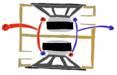
I put the ports on the side just for fun... then they create two dipolar radiation patterns depending on the frequency being played. This could also be done with sealed subs also I suppose, but what a waste of energy. Below tuning.... I guess these subs would still act like dipoles, who knows what kind of low end is achieveable.... If i had two identical subs I'd build one and let you know
Configuration
Rudulf,
The photos of Axel and his ripoles seem to show the unit not as 2 N cabinets but a reduced W. What I mean is that both woofers look like they fire into one another with no panel between them. I believe that it also looks like the air space between the woofers is curved at the back so that a half-circle is formed. Does this describe the model that you have tried?
Thanks, Randy
BA, basically you have two vented subs next to each other which are wired with the polarity reversed on one, correct?
If this is so ...
I can't see any advantage over just using a H baffle dipole - you have used 2 drivers to achieve what a H baffle does with one. Due to the nature of the vented box, cone movement will be restricted more, and power handling will be higher, however this will be at the cost of efficiency. In essence you need more power to do the same job, but at the same time the transient response will not be as good.
Re: Configuration
thats correct. They ARE reduced W-baffles, but with a minimized air volume in front and back of the woofers.
I see that in the picture the cabinets look as if they are curved at the back, but they are just square. No half-circle in it.
Rudolf
Randy,Jazr said:both woofers look like they fire into one another with no panel between them
thats correct. They ARE reduced W-baffles, but with a minimized air volume in front and back of the woofers.
I see that in the picture the cabinets look as if they are curved at the back, but they are just square. No half-circle in it.
Rudolf
I think this design could give some funky response or perhaps it might be smooth, you never know until you try right.... or does everyone just rely on simulations nowadays? i think i shall make a small trial version of this for my extremis midwoofers.... not really suited for dipole use, but if it doesnt work out I can simply reverse the polarity and use normally
- Status
- This old topic is closed. If you want to reopen this topic, contact a moderator using the "Report Post" button.
- Home
- Loudspeakers
- Subwoofers
- Ripoles - Honey, I shrunk the dipoles! #1