
I´d like to add the abscense off large series resistances found in all other passive networks.
If the input stage is a current source amp instead of a voltage source the large series resistor becomes a shunt resistor. Kevin Carter has used this approach with his K&K Audio phono preamps.
Another option to play with is a lower impedance LR network used as part of the feedback for a gain cell. A project like this appeared in Audio Amateur a few years ago, and I did a take on it in a thread posted here:
Another Wrench In the Works... Inductive RIAA
Food for thought, and grounds for further research...
Another Wrench In the Works... Inductive RIAA
Food for thought, and grounds for further research...
Last edited:
Thread's referenced now - this is a project I haven't gotten around to building as of yet - don't see any reason why it wouldn't basically work, though it would be interesting to see the effects of inductor stray C on RIAA accuracy.. The Audio Amateur preamp used OPA627 with low impedance LR as the bottom element of the feedback, I used it in two places in a split implementation.
I read about the LCR filters time ago. I think the foundation of RLC phono is the O. Zobel articles in Bell Labs Journal about constant impedance networks. The wikipedia covers this.
As this filters are contant impedance, the product LC is constant:
L=R(t2-t1)
C=(t2-t1)/R,
where t1=318us and t2=10t1. (This is the bridged T network for t1 and t2).
So there is a compromise. You have to choose: big capacitors or inductance loses. Maybe the R=600 Ohm is such compromise.
As this filters are contant impedance, the product LC is constant:
L=R(t2-t1)
C=(t2-t1)/R,
where t1=318us and t2=10t1. (This is the bridged T network for t1 and t2).
So there is a compromise. You have to choose: big capacitors or inductance loses. Maybe the R=600 Ohm is such compromise.
Thread's referenced now - this is a project I haven't gotten around to building as of yet - don't see any reason why it wouldn't basically work, though it would be interesting to see the effects of inductor stray C on RIAA accuracy.. The Audio Amateur preamp used OPA627 with low impedance LR as the bottom element of the feedback, I used it in two places in a split implementation.
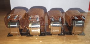
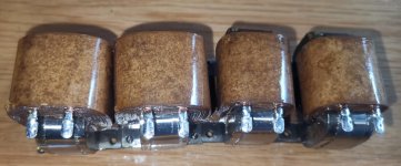
The inductor stray C on RIAA is crucial. I produced a couple coils with one or more sections. At the end I used for the coils 2 sections. For the high inductive I got a stray C of 17pF, for the other 8.3p. Excellent and in line with LTSpice simulation. Not any problem within the audio frequency, mensurabel above 80kHz.
Not sure if this RF chokes can be used. I will try the 100mH (+/- 10%), are cheap and you don't have to wind:
https://www.mouser.com/ds/2/54/250_series-777031.pdf
Don't know if 79 Khz is too low for SRF. The dc resistance is big, the gain will be affected.
https://www.mouser.com/ds/2/54/250_series-777031.pdf
Don't know if 79 Khz is too low for SRF. The dc resistance is big, the gain will be affected.
RL circuits are in principle not different from RC ones, but practically there are two important issues. 1) Inductance of a coil is not a set value like capacitance of a capacitor; it changes with frequency and signal level; 2) Inductors have considerable winding capacitance. Because of these issues, inductors cannot be made to exactly match the calculated values, and need trimming to achieve the desired frequency response.
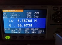
Have one question here.if we build the L,what is the test spec,which means for the 1.8H/45mH inductors,how to musure measure if we use the LCR meter.How to set the musure frequency and voltage,100Hz/1V for the 1.8H or 1Khz/1v for 45mH.
I ask this question due to I musured my ordered inductors,if I set different test frequency and voltage,the test result is different.
I ask this question due to I musured my ordered inductors,if I set different test frequency and voltage,the test result is different.
Have one question here.if we build the L,what is the test spec,which means for the 1.8H/45mH inductors,how to musure measure if we use the LCR meter.How to set the musure frequency and voltage,100Hz/1V for the 1.8H or 1Khz/1v for 45mH.
I ask this question due to I musured my ordered inductors,if I set different test frequency and voltage,the test result is different.
Hello. Even 45mH inductors have enough turns and layers that they have some parasitic capacitance. This creates a resonance at relatively low frequency. This resonance spreads down enough (the Q is not super high) so when you measure at 1kHz you have the capacitive part starting to effect the measurements. Therefore the inductance looks lower b/c the meter does not compensate for the impedance due to the capacitance. Your 100Hz measurement is more correct.
The 1.8H inductor will really show a difference when measuring at 100Hz vs 1kHz.
Btw the capacitive part, and thus resonance, is completely swamped by the driving tube (or transistor) and load, so in practice it is of no real worry. (Assuming you don't have crazy high impedances driving and loading).

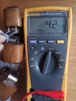
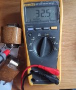
I plan to use the a litter bit high impedance.I summarize the the different test frequency and test voltages.Details please refer to the attached photos.
Attachments

- Home
- Source & Line
- Analogue Source
- RIAA LCR Mythos