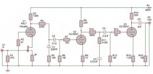
Circuit
Hi Corbato,
Using a 100k with 100k resistor will severly lessen the high frequency response. The feedback circuit won't work on this problem. Look below at some figures of high frequency loss.
Consider a stage of gain of only 10, with 4pf grid to plate capacitance (two tubes in parallel so twice the gp capacitance) and no stray capacitance (very optimistic). I have computed (computer program) the -1db and -3db responses.
1) with 100k volume control set to midpoint
-1db = approx 6khz
-3db = approx 14khz
2) 100k pot set with wiper 30k from ground to wiper arm (70k to source) and 100k resistor to grid
-1db = approx 6khz
-3db = approx 14.5khz
3) 100k pot set with wiper 30k from ground and 70k to source, 1k to grid
-1db = approx 43.5khz
-3db = approx 86khz
Test "2 and 3" seems ok but as the volume pot is varied, the HF response will change dramatically as indicated in the tests. Since you don't know where the volume control will be set, the HF response can vary wildly. I would definitely not use a 100k resistor to the grid.
Also remember that all other sources, stages also degrade the HF performance and -db are additionally cumulitive. The figures I present don't even include the HF response of the 6sn7 to the following stage (amp input including the IC capacitances).
Hope this helps.
Using a 100k with 100k resistor will severly lessen the high frequency response.
Yes it will, it is not a good solution in this case.
The feedback circuit won't work on this problem.
It will to the same degree as the gain is lowered, the Miller capacitance is determined by the stage gain, not by u.
A better solution for a wideband line stage is to use for instance 2 gain stages with heavy cathode coupled feedback, in that case the Miller effect can be in practise eliminated, another solution is to use a cathode follower as an input stage. The idea of a large resistor in series with the grid is a bad idea anyway as it is difficult to get below ~5-10pF including stray capacitance, even without a resistor a 100kohm pot is not ideal if you want to have high constant bandwidth.
My own line gain stage has an open loop gain of ~2000 but I use heavy feedback to reduce this to as low as 4 when I use it to amplify signals from a CD player, the input capacitance is of course neglible in this case and approaches Cgp only. I use a 100kohm pot and I can achieve a constant bandwidth of ~200 kHz which is more then enough for me.
Regards Hans
Konnichiwa,
I don't think so. The "requirements where set out clearly:
1) Phono & Line (eg. generic "full function" preamp)
2) Use certain Valves
3) Don't use Interstage etc. Transformers
Invariably the answer is that at some point in time it MIGHT BE required to do so.
Most Moving Magnet Cartridges require a lot of capacitance as load (even modern ones) to give a balanced response. This is becaus ethey all use the resonance between their Coils inductance and the external capacitance as resonant circuit to bring the High Frequencies up.
Most MM are in the region of 0.5 - 0.8H and require a resonance at around 15 - 18KHz. This implies quite high capacitive loads, old SME Arms came with a PAIR of 250pF Capacitrs conneted in parallel to the cable, if there was not enough treble you simply clipped one out.
Anyway, in my suggested ECC83/ECC88 Phono Circuit the ECC83 operates at a stage-gain of around 37 (due to local feedback and lowish anode load), resulting in around 60pF Miller amplified input capacitance plus a few puff (pF) extra for the other capacitances. Even with 175pF Arm/Cable capaictance this is by far too low to work with most MM's, requiring extra capacitive load. So the Miller Capacitance is not an issue.
I still feel that the choice of Valves and refusal to allow transformers will severely limit the possible performance, but I think it is not difficult to fulfill the requirements.
Sayonara
EC8010 said:I can't help feel that there's been a lot of fuss and bother before full requirements have been determined.
I don't think so. The "requirements where set out clearly:
1) Phono & Line (eg. generic "full function" preamp)
2) Use certain Valves
3) Don't use Interstage etc. Transformers
EC8010 said:Does the pre-amplifier need to drive significant capacitance?
Invariably the answer is that at some point in time it MIGHT BE required to do so.
EC8010 said:Is the arm capacitance confirmed as 175pF?
Most Moving Magnet Cartridges require a lot of capacitance as load (even modern ones) to give a balanced response. This is becaus ethey all use the resonance between their Coils inductance and the external capacitance as resonant circuit to bring the High Frequencies up.
Most MM are in the region of 0.5 - 0.8H and require a resonance at around 15 - 18KHz. This implies quite high capacitive loads, old SME Arms came with a PAIR of 250pF Capacitrs conneted in parallel to the cable, if there was not enough treble you simply clipped one out.
Anyway, in my suggested ECC83/ECC88 Phono Circuit the ECC83 operates at a stage-gain of around 37 (due to local feedback and lowish anode load), resulting in around 60pF Miller amplified input capacitance plus a few puff (pF) extra for the other capacitances. Even with 175pF Arm/Cable capaictance this is by far too low to work with most MM's, requiring extra capacitive load. So the Miller Capacitance is not an issue.
I still feel that the choice of Valves and refusal to allow transformers will severely limit the possible performance, but I think it is not difficult to fulfill the requirements.
Sayonara
Re: Re: RIAA and Linestage for life time
I have an excellent source of pure audiophile grade viagra. Want some")
The pre amp will be placed just next to the TT and will have outboard PS.
Ok. While its emerging that mix and match tubes are in thing, how about this for a Phono?
Thanks Thorsten Sahib for the schematic. I think I'd avoid teh 100K input grid resistor and look out for 500K pot. Your suggestions pls?Kuei Yang Wang said:How about a parallel 6SN7 or ECC88/6DJ8
Exactly. Particularly when I realise that I've an almost unlimited source of NOS 6SN7/6SL7's.thoriated said:Maybe 6SN7's 6SL7's
fdegrove said:that I should definitely try out that latest HGH hormone that promises me eternal youth...Ooops, wrong forum.
I have an excellent source of pure audiophile grade viagra. Want some
Tube regulated supplies? With OA2's and such. Why not.Naturally, I'd stick more valves in the PSU than in the circuit proper...That's just me though...
The pre amp will be placed just next to the TT and will have outboard PS.
Ok. While its emerging that mix and match tubes are in thing, how about this for a Phono?
Attachments
Cascodes in the first hole do have an advantage in that the Millering problem is much reduced. Getting low-noise performance from 6SL7s can be quite an exercise and one I might hesitate to undertake. The reason I asked about FETs before is that the bottom of an input cascode is the perfect place to use a low-noise FET. Let the tube do what it does best, swing a lot of voltage, and the FET do what it does best, drive current out of its drain with a high gm. Low Millering means great flexibility in choosing input capacitance.
For mm use, a VERY inexpensive FET which is easy to get and very quiet is the NTE458. In my preamp, I cascode this with a 6DJ8-type tube on the top.
For mm use, a VERY inexpensive FET which is easy to get and very quiet is the NTE458. In my preamp, I cascode this with a 6DJ8-type tube on the top.
Re: Re: Re: RIAA and Linestage for life time
Konnichiwa,
Vishay/Sfernice P11 Cermet track.
I prefer passive filtering with enough capacitance and high quality cap's, especially in the final position.
Hmmm. the 6SL7 in the first stage is not going to bias at much voltage and the current will be low. That will severely prejudice any FET you could possibly use there. You could lift up the 6SL7 Grid of course, but that will add complexity and will still not solve the low current issue. In the interest of overload margins and noise I'd swap the positions of the two RIAA.sections as well
Secondly, most low noise FET's have a rather stratospheric transconductance which would make your circuit have by far too much gain, even for MC Pickups, let's say a FET with a gm (Yfs) of 10mA/V is used, the gain of the first cascode stage will be 1000. Even if we follow this with the 3180/318uS RIAA section the signal send into the forst 6SN7 would be at around 100 times the input voltage, then amplified by at least aanother factor, so for a MM Input you would have around 60db gain after the second stage and 80db after the third stage. Even or MC pickups this is BY FAR excessive.
Further, the final stage will have a rather high output Impedance.
If you insist on having a J-Fet in there (which is not at all needed for MM BTW) drop at least one stage, use a compound RIAA similar to that shown in my Phono and use 6SN7 in both stages, bypass the second stages cathode resistor, 47k Load, 1K cathode resistor & 250V +B.
The J-Fet should be 2SK170 with around 5mA Idss (BL Grade), no source resistor and the Cascode 6SN7 should have around 10k Anode Load. The 6SN7 should bias up suitably to have enough operating Voltage for the FET. The resultant Phono will have minimal input capaitance (a bad thing for a MM phono BTW as you will need to add load capacitors) and around 54db gain.
Sayonara
Konnichiwa,
corbato said:Thanks Thorsten Sahib for the schematic. I think I'd avoid teh 100K input grid resistor and look out for 500K pot. Your suggestions pls?
Vishay/Sfernice P11 Cermet track.
corbato said:Tube regulated supplies? With OA2's and such. Why not.
I prefer passive filtering with enough capacitance and high quality cap's, especially in the final position.
corbato said:Ok. While its emerging that mix and match tubes are in thing, how about this for a Phono
Hmmm. the 6SL7 in the first stage is not going to bias at much voltage and the current will be low. That will severely prejudice any FET you could possibly use there. You could lift up the 6SL7 Grid of course, but that will add complexity and will still not solve the low current issue. In the interest of overload margins and noise I'd swap the positions of the two RIAA.sections as well
Secondly, most low noise FET's have a rather stratospheric transconductance which would make your circuit have by far too much gain, even for MC Pickups, let's say a FET with a gm (Yfs) of 10mA/V is used, the gain of the first cascode stage will be 1000. Even if we follow this with the 3180/318uS RIAA section the signal send into the forst 6SN7 would be at around 100 times the input voltage, then amplified by at least aanother factor, so for a MM Input you would have around 60db gain after the second stage and 80db after the third stage. Even or MC pickups this is BY FAR excessive.
Further, the final stage will have a rather high output Impedance.
If you insist on having a J-Fet in there (which is not at all needed for MM BTW) drop at least one stage, use a compound RIAA similar to that shown in my Phono and use 6SN7 in both stages, bypass the second stages cathode resistor, 47k Load, 1K cathode resistor & 250V +B.
The J-Fet should be 2SK170 with around 5mA Idss (BL Grade), no source resistor and the Cascode 6SN7 should have around 10k Anode Load. The 6SN7 should bias up suitably to have enough operating Voltage for the FET. The resultant Phono will have minimal input capaitance (a bad thing for a MM phono BTW as you will need to add load capacitors) and around 54db gain.
Sayonara
Biasing up the grid of the first stage tube is pretty easy. In my preamp, there's a 12V rail used to power the heaters. I bring a 680K resistor from that rail to the first stage grid, then bypass the grid with a 0.33u cap. Two extra parts, no big deal.
The transconductance issue is similarly easy to dispose of. First, recognize that the gm is nowhere near the spec if you're not running at idss. Second, because of the levels here, you can sacrifice a miniscule degradation in noise to have some degeneration in the source lead. For the FET I specified (NTE458), a 6DJ8-family tube, a 620 ohm source resistor, a 100K plate resistor, and a 230V B+, I get a gain of 110, almost exactly what I targeted. The stage has no trouble swinging +/-50V, so overload is not likely to be an issue. Noise is low enough that at normal volume settings, I need to get my ear within a few inches of the speaker to hear any noise.
The transconductance issue is similarly easy to dispose of. First, recognize that the gm is nowhere near the spec if you're not running at idss. Second, because of the levels here, you can sacrifice a miniscule degradation in noise to have some degeneration in the source lead. For the FET I specified (NTE458), a 6DJ8-family tube, a 620 ohm source resistor, a 100K plate resistor, and a 230V B+, I get a gain of 110, almost exactly what I targeted. The stage has no trouble swinging +/-50V, so overload is not likely to be an issue. Noise is low enough that at normal volume settings, I need to get my ear within a few inches of the speaker to hear any noise.
- Status
- This old topic is closed. If you want to reopen this topic, contact a moderator using the "Report Post" button.
- Home
- Amplifiers
- Tubes / Valves
- RIAA and Linestage for life time