I picked up this dandy over Thanksgiving weekend for a hot $25. It seems to have been designed as an auxiliary unit for a console TV/radio/turntable, and is only a single channel. I'm enjoying it currently, but would like to get it into the best possible shape I can while keeping its limitations in mind. I typically work with vintage guitar and bass amps, so I've been having a lot of fun learning about tube gear made for clean headroom rather than overdrive.
This particular amp couldn't have been used in recent years considering the scratchy pots and overwhelming hum, so I cleaned it up, replaced the filter caps and added a grounded power cord and an inline fuse while I was in there. There is still some hum/buzz that I have to track down, so I'm digging through other posts before I ask questions that will get my primary reasons for posting off track.
Having not worked on anything quite like this, what can those more experienced than me tell me about the design itself? Anything good, bad, or otherwise that you can tell me? I haven't gone through everything point by point yet internally, but I can say all of the capacitors are ceramic discs, which I haven't worked with a whole lot. Any improvement to the tone stack by changing things for different values/types of capacitors? The only part that appears to be totally useless is the input switch (LP/RIAA/78), but correct me if I'm mistaken. The tubes seem to be doing well, and are all original USA or West German tubes rebranded "Dynamic Electronics".
Lastly, it has two full range 8" speakers in the open baffle cabinet wired in series running at ~6ohm. The schematic states "6-8ohm", which I've never really seen stated as a range... Any idea what an OT like this handle? I was looking at replacement options and came across the Wild Burro "Betsy". Running one of them would put me just shy of 6ohm, but a pair to fill the cabinet would get me just short of 12ohm. Bad idea on the latter, or not a big deal? I have never dealt with impedance mismatches before, so if I'm missing any important information I'd be happy to track it down.
Thanks in advance for your replies!
An externally hosted image should be here but it was not working when we last tested it.
This particular amp couldn't have been used in recent years considering the scratchy pots and overwhelming hum, so I cleaned it up, replaced the filter caps and added a grounded power cord and an inline fuse while I was in there. There is still some hum/buzz that I have to track down, so I'm digging through other posts before I ask questions that will get my primary reasons for posting off track.
Having not worked on anything quite like this, what can those more experienced than me tell me about the design itself? Anything good, bad, or otherwise that you can tell me? I haven't gone through everything point by point yet internally, but I can say all of the capacitors are ceramic discs, which I haven't worked with a whole lot. Any improvement to the tone stack by changing things for different values/types of capacitors? The only part that appears to be totally useless is the input switch (LP/RIAA/78), but correct me if I'm mistaken. The tubes seem to be doing well, and are all original USA or West German tubes rebranded "Dynamic Electronics".
An externally hosted image should be here but it was not working when we last tested it.
Lastly, it has two full range 8" speakers in the open baffle cabinet wired in series running at ~6ohm. The schematic states "6-8ohm", which I've never really seen stated as a range... Any idea what an OT like this handle? I was looking at replacement options and came across the Wild Burro "Betsy". Running one of them would put me just shy of 6ohm, but a pair to fill the cabinet would get me just short of 12ohm. Bad idea on the latter, or not a big deal? I have never dealt with impedance mismatches before, so if I'm missing any important information I'd be happy to track it down.
Thanks in advance for your replies!
Let's start with physical danger. C15 & C16 are known as death capacitors. They must be eliminated. That you've already installed a proper, 3 wire, safety grounded, power cord is good.
That looks like a self splitting O/P stage. Therefore power O/P capability is halved.
Stay with the documented speaker impedance range. Either series wired 4 Ω drivers or parallel wired 16 Ω drivers will do the job, as replacements. When the unit was new, 3.2 Ω drivers were quite prevalent.
Is space available to "shoehorn" in a choke? A CLC filter, instead of a cheap simple cap., should reduce the 120 Hz. buzz level.
Ceramic caps. are frowned upon in interstage coupling positions. Replacement by 716P series Orange Drops rates to be an improvement.
The switch you commented on is a crude accommodation of the different EQ curves used, before RIAA EQ became standard. Leave it in the RIAA position or defeat it.
That looks like a self splitting O/P stage. Therefore power O/P capability is halved.
Eli knows much more than i do...
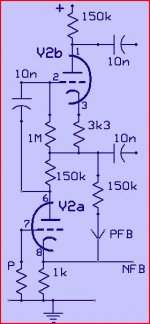
If you can sacrifice the gain -- likely with modern sources -- and the OPT can handle the extra power, one could convert to a concertina phase splitter. One would start with the rewiring in red changing the load Rs, and then fix up the tube's bias appropriately.
dave
Attachments
That looks like a self splitting O/P stage. Therefore power O/P capability is halved
Maybe i'm wrong , to me seems like the PI is a concertina ac coupled, the weird thing is the way the first 12ax7 plate is supplied...
Eli knows much more than i do.
Rubbish!
If you can sacrifice the gain -- likely with modern sources
The O/P of the crystal carts. used with that unit is roughly the same as that of a CDP. It could easily be the case that gain can't be spared. Notice the unbypassed cathode bias resistors. Fortunately, adding a "concertina" phase splitter can be done easily enough. A ZVN0545A will achieve the desired result, while imposing no added heater draw burden.
I suspect the OEM O/P trafo can't handle "15" W. The fact that phase compensation is present is incongruous, in an inexpensive unit. A photo of the O/P "iron" would be useful.
Maybe i'm wrong , to me seems like the PI is a concertina ac coupled, the weird thing is the way the first 12ax7 plate is supplied...
C14 places V4's g1 at or near AC ground potential. Seems self splitting to me.
Thanks for the helpful replies, all! I should have mentioned that I did remove C15 and C16 while adding the fuse and grounded cord. If you didn't figure this out, sakellog, death caps are referred to as such because they can send voltage through anything connected to the amplifier if/when they fail. If this was a guitar amp and you had a guitar plugged into it, there's a decent chance you would get a nasty shock when you ground yourself to something else.
Excuse my beginners attempt at dissecting the circuit, Eli, but when you're referring to coupling capacitors in this schem, would they be C7, C10, C13, and C14? I assume the others leading to ground are fine as long as they're functional, correct? There is definitely room to mount a choke, but I'll have to read up on implementing that and your comment about the concertina phase splitter.
I'll take things apart and get some pictures of the transformers soon. The OT is about the size of chokes I've had on larger amps, so I'm guessing it's not going to handle very much power. The speakers in it now are indeed quite efficient, so it does put out a considerable amount of volume. I'll work on finding replacements within the spec on the schematic, and may end up looking into a different OT if I want to run a different load.
.JPG)
Maybe i'm wrong , to me seems like the PI is a concertina ac coupled, the weird thing is the way the first 12ax7 plate is supplied...
It is a concertina phase splitter, the output stage is not self splitting and the driver stage tubes appear in series from a DC standpoint, but from an AC standpoint the concertina cathode is bootstrapping the plate load resistor of the voltage amplifier stage. (Gain in the first stage could be close to mu)
Based on the schematic it seems that the intent was to connect this directly to a crystal or ceramic cartridge, and with the substantial insertion loss of the passive tone controls every means of maximizing gain in the successive stages seem to have been taken.
It's a "Dynamic Electronics Series 400 Stereo High Fidelity System". The RCA input on the back says "stereo input", but clearly it's using stereo as a noun rather than a verb. Perhaps you're correct about the attempt at maximizing gain, since the LP input setting seems to be the only one that generates reasonable volume levels -- RIAA and 78 are very faint.
That circuit, with enough supply, is capable of 10-11W. Here is a "modern" one:
EL84 Push-Pull
Click on the images to zoom up...
EL84 Push-Pull
Click on the images to zoom up...
I think there's a drawing error in the schematics. V2A won't draw any plate current in the shown configuration. R14's cold end shold relate to Eb instead of ground (or something like that). Then the operation priciple becomes clear: V2A is a voltage amplifier, with R12 as cathode and R14 as plate resistors, V2B is a Concertina, with R 15 as cathode and R20 as plate resistors.
Best regards!
Best regards!
It looks to me that the RIAA setting should be the loudest with no attenuation on it. Maybe the switch's contacts are dirty?
Ceramic cartridge levels were quite high, but on average not much higher than CD levels so it sounds like something is amiss.
I think there's a drawing error in the schematics. V2A won't draw any plate current in the shown configuration. R14's cold end shold relate to Eb instead of ground (or something like that). Then the operation priciple becomes clear: V2A is a voltage amplifier, with R12 as cathode and R14 as plate resistors, V2B is a Concertina, with R 15 as cathode and R20 as plate resistors.
Best regards!
Have another look, it's basically a perversion of a mu follower with differential outputs. I'm pretty confident it works, and it is actually rather clever IMO.
- Status
- This old topic is closed. If you want to reopen this topic, contact a moderator using the "Report Post" button.
- Home
- Amplifiers
- Tubes / Valves
- Reviving a late 50's el84-based hifi