It looks like everything fit in nicely! I haven't built this amp yet myself but I think the offset connector is just for measuring DC offset. Try unplugging the speaker relay ribbon cable first and see if the amp will power up properly. If it does, verify there is no DC present on the outputs. Ribbon cable length doesn't matter.
I have the Amp control and DC detection boards installed in chassis for the Tribute 3000. On the Tribute 3000 OPS there is a 2 wire pin labeled OFFSET. Should these be connected to anything?
When I turn on the amp the relays click and after about 5 seconds click again and I get a rapidly blinking LED, DC offset alarm I believe.
Bias and DC Offset were set before I installed the amp control boards and Jeff had adjusted and tested those. So I'm thinking it must be a wiring mistake.
Jeff is right - the OFFSET pins are just for measuring the offset with DMM.
I would recommend disconnecting the amplifier and trying to troubleshoot the control board standalone. Connect the main rails, connect the board offset-sensing inputs to ground (zero offsets) and power-on the thing. You should have it running smoothly.
As the next testing exercise, you can disconnect one input from the ground and connect it to some DC source - protection will trigger.
As the next testing exercise, you can disconnect one input from the ground and connect it to some DC source - protection will trigger.
Me too!I would recommend disconnecting the amplifier and trying to troubleshoot the control board standalone. Connect the main rails, connect the board offset-sensing inputs to ground (zero offsets) and power-on the thing. You should have it running smoothly.
As the next testing exercise, you can disconnect one input from the ground and connect it to some DC source - protection will trigger.
Testing the protection board stand alone is an easy way,then you will know where the problem come from.
")
It's actually easier to unplug the relay boards and see if it powers up, power down and connect one relay board and repeat. If it powers up connect the last relay board and repeat. That will let you know which channel is the issue. A quick measurement of the output offset on the offending channel will tell you if the issue is in the relay board or amp without having to dismantle anything.
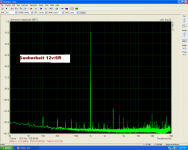
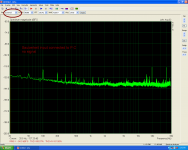
Sauberkeit
According Valery's guides.
D1,D4 SHORTED
C11,C12=100pf
C15 REMOVED.
This is a stand alone test.
According Valery's guides.
D1,D4 SHORTED
C11,C12=100pf
C15 REMOVED.
This is a stand alone test.
Attachments
Last edited:
According Valery's guides.
D1,D4 SHORTED
C11,C12=100pf
C15 REMOVED.
This is a stand alone test.
Hi Thimios! Thank you for the info.
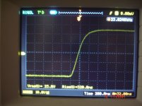
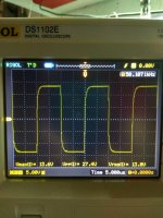
Showing a bit of an overshoot, being lightning fast at the same time.
Let's test it together with OPS, and then we'll see.
Probably we will return C15 at some small value, but let's see the whole thing first.
Hi Thimios,
I have a similar Rigol scope. Do you know how to record DC voltage for lets say a few minutes and save on USB?
Thanks
Do
Hi Do,no i don't know if this(recording) is an existing procedure on my scope,i know the way for storage only.
Now attached to OPS.
No good news
Well, it's much better than it was before, isn't it?
Now you can put some 15-22pF as C15 for having the front corners more rounded.
More pictures
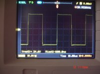
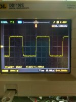
1)50Khz
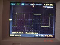
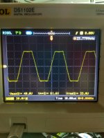
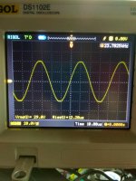
2)soft clip
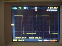
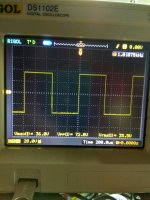
3)1Khz
Rather fast and accurate, huh?
I like it.
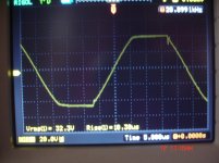
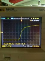
Yes but what is the unnormal rise on picture 3 on post#2828?
That's not an issue - the whole thing happens within a very short timeframe.
The bottom half of the slope takes around 100nS - holy shoot!
Then it slows down a bit, forming some kind of inflection point. It may be possible to smooth it by tuning-up the compensation, however even as-is it will not create any issues within the audio range of frequencies.
50KHz square in the post#2831 looks very good, as well as 1KHz - super accurate.
Ok boss!
What about C15,do you see any reason for additing something here?
I would test with, say, 15pF just for the sake of curiosity if it's going to make that inflection point less noticeable in the same conditions.
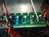
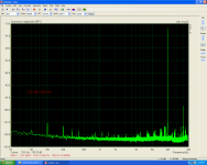
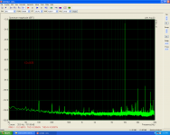
Sauberkeit+NS
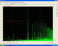
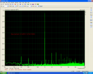
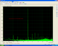
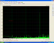
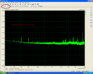
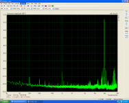
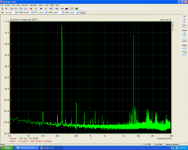
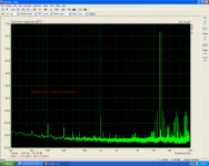
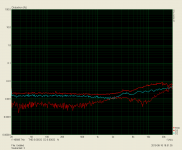
Let's see what is the new IPS.
Power supply +/-50v
32.000UF/RAIL
Idle=70mA
Offset=3mV.
The rest on the pictures.
Picture 1,2 how quiet is the amplifier.
Let's see what is the new IPS.
Power supply +/-50v
32.000UF/RAIL
Idle=70mA
Offset=3mV.
The rest on the pictures.
Picture 1,2 how quiet is the amplifier.
Attachments
-
 140W.PNG116.4 KB · Views: 84
 -
 121W.PNG107.8 KB · Views: 85
 -
 96W.PNG108 KB · Views: 75
 -
 1w 1 k.PNG106.9 KB · Views: 73
 -
 2.6V.PNG107.6 KB · Views: 73
 -
 12v 20k.PNG107.4 KB · Views: 73
 -
 12V 10K.PNG109.3 KB · Views: 98
 -
 12v.PNG107.2 KB · Views: 99
 -
 INP GTO P.C NO SIG.PNG110.2 KB · Views: 93
 -
 inp short.PNG109.2 KB · Views: 287
Last edited:
- Home
- Amplifiers
- Solid State
- Revisiting some "old" ideas from 1970's - IPS, OPS