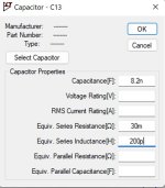
Before going into different DSD rates with even smaller timesteps, I first wanted to get a better feeling whether a more realistic 8.2nF cap as against an ideal version would make any difference.
That's why I added a 30mR series resistance and a 200pH series inductance, this according to Kemet specs for their 8.2nF NP0.
Result turns out to be rather obvious as shown in the attachment below, without at the left side and with these two series impedances at the right, where lots of spikes are visible at the moment the slope inverts its direction.
These spikes feedthrough all the way into the first OPA2210 op-amp.
Image was made with a 50psec timestep while processing the DSD256 1Khz@0dB signal.
Blue is the signal as measured on the 8n2cap.
Red is the signal on the inverting input of the OPA2210, connected with a 255R to the 8n2 cap, here for better clarity magnified by a factor 10
Looking only at the red curves, those spikes look quite small compared to the triangular ripple you already get with ideal capacitors. It looks to me like the series inductance isn't dominant.
2 mV peak-peak isn't a lot, but the distortion components bohrok2610 found aren't very large either, and the voltage-to-current characteristics of bipolar transistors are very curved.
As mentioned in the text, I only added to the 8.2nF a series resistance and a series inductance.How did you model the parasitics of the capacitors, resistors and IC package?
Attachments
Yes these spikes are small, and with your PWM8 generated files they will also occur, so this will never be the reason for Bohrok’s distortion products.Looking only at the red curves, those spikes look quite small compared to the triangular ripple you already get with ideal capacitors. It looks to me like the series inductance isn't dominant.
2 mV peak-peak isn't a lot, but the distortion components bohrok2610 found aren't very large either, and the voltage-to-current characteristics of bipolar transistors are very curved.
The only thing I wondered if these spikes can be the reason for the S/N going down a bit when DSD rate goes up, because in the same play time DSD256 has 4 times as many spikes as DSD64.
Hans
I can only give a rather long answer to that, an answer which might result in a very long discussion that we already had a couple of years ago.
In my opinion, spikes as such are no problem, but some second-order effects related to spikes may be.
Suppose there were some difference between the low-to-high and high-to-low transitions, but that that difference was perfectly the same for all flip-flops and perfectly reproducible from cycle to cycle, and that the output filter was perfectly linear. In that case, you would get spikes due to the difference between low-to-high and high-to-low transitions, but it would not do any harm whatsoever. All ones would still have the same weight, albeit a weight that is slightly different from the weight with ideal pulses, all zeros would still have the opposite weight, and the waveform of the current drawn out of the reference would still be exactly the same in each bit clock cycle.
If the spikes would cause distortion in a not so perfectly linear output filter, they could contribute to noise as well as low-level distortion, but as the triangles are much larger than the spikes, I would expect this not to be dominant.
Now imagine the low-to-high delay would depend on the switching threshold of some tiny logic gate somewhere inside the 74LV574A, and the gate's switching threshold would depend on the 1/f-noise of its MOS transistors. You could then have an effect that converts the 1/f-noise of those MOS transistors into audio noise, and does so more effectively at high bit clock rates.
Suppose the delay were dependent on the previous bit due to imperfect internal settling of the flip-flops, like ThorstenL wrote about. You would then have a nonlinear effect that gets worse at higher bit clock rates and that could cause conversion of out-of-band quantization noise down to the audio band. Its dependence on the bit clock frequency would presumably be rather extreme, unlike the smooth dependence of the 1/f-noise conversion.
A second-order effect that should theoretically be harmless is the time dependence of the filter due to the transitions of the shift register outputs. During the transitions, the output impedance of a CMOS output goes from low to much higher and back to low. I think it's harmless because it happens at a multiple of the clock rate; the filter time-dependence can't mix any rubbish down to the audio band, because around exact multiples of the clock rate, you only have images of the audio spectrum.
Now imagine the low-to-high delay would depend on the switching threshold of some tiny logic gate somewhere inside the 74LV574A, and the gate's switching threshold would depend on the 1/f-noise of its MOS transistors. You could then have an effect that converts the 1/f-noise of those MOS transistors into audio noise, and does so more effectively at high bit clock rates.
I would worry more about PCB layout and ground/supply bounce in lead frame and bond wires. But there is a LOT to cause us grief here and it's inside a black box we call IC.
Suppose the delay were dependent on the previous bit due to imperfect internal settling of the flip-flops, like ThorstenL wrote about.
Not so much imperfect setting, but data dependent shift of thresholds.
You would then have a nonlinear effect that gets worse at higher bit clock rates and that could cause conversion of out-of-band quantization noise down to the audio band. Its dependence on the bit clock frequency would presumably be rather extreme, unlike the smooth dependence of the 1/f-noise conversion.
Yes, that I was able to observe. 1/f noise tends to cause skirts, the switching speed stuff I observed raised overall FFT noise floor with the longest settings for averaging on AP2 and in the in-house audio tester hardware I designed in combination with WaveGene/Wavespectra.
I observed this with both active output stages and purely passive LC filtering between FIR DAC and active circuits.
I did not pursue identifying the underlying mechanisms but simply noted it as a limitation of the specific parts and applied a different workaround.
A second-order effect that should theoretically be harmless is the time dependence of the filter due to the transitions of the shift register outputs.
As long as the time dependence is sufficiently random, yes. What if this is data dependent?
Thor
I would agree that Marcel's dac, good as it is, has a little distortion (and or noise that sounds like distortion) which is independent of the output stage. IME, the output stage makes the sound worse in a complex way which to me suggests to me multiple mechanisms may be involved (like for instance the sound of DC blocking caps in the final stage which some people choose to bypass). Maybe the sound of the caps can be explained by group delay effects, microphonics, DA, whatever, just maybe not HD.
As long as the time dependence is sufficiently random, yes. What if this is data dependent?
Thor
My line of reasoning holds when it is perfectly regular, the time constant of the first part of the analogue filter getting disturbed by the same amount for the same time in every clock cycle.
IME, the output stage makes the sound worse in a complex way which to me suggests to me multiple mechanisms may be involved (like for instance the sound of DC blocking caps in the final stage which some people choose to bypass). Maybe the sound of the caps can be explained by group delay effects, microphonics, DA, whatever, just maybe not HD.
How about soft tones that get frequency modulated by the audio signal being added to the audio signal? Isn't that sufficiently complex?
In any case, I intend to make a new filter with more passive filtering before the first active part. It will probably be something largely discrete and operating in class A. No idea when it will be finished.
Yes. Didn't mean to suggest otherwise. Just want to see the already very good dac become the best it can be. In that regard, exciting to hear you have an idea for a different output stage conceptIsn't that sufficiently complex?
")
Hoere's hoping a cross quad is includedHow about soft tones that get frequency modulated by the audio signal being added to the audio signal? Isn't that sufficiently complex?
In any case, I intend to make a new filter with more passive filtering before the first active part. It will probably be something largely discrete and operating in class A. No idea when it will be finished.
That OPA1632 stage has same topology as I suggested in #2048 and what I used in my output stage shootout. So why the name?This is the one I used.
Sorry for giving all the credit to Thor, your filter was already quite close but Thor added the three 10nF input caps instead of one single 1nF.
That seems to make quite a difference, but I'll come back to that.
I'll rename the filter immediately to "Alternative Filter" and give the kudos to you.
Hans
That seems to make quite a difference, but I'll come back to that.
I'll rename the filter immediately to "Alternative Filter" and give the kudos to you.
Hans
Looking at the schematic Thor did not add any caps but changed 8.2nF caps to 10nF and 1nF cap to 10nF.Thor added the three 10nF input caps instead of one single 1nF.
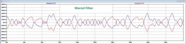
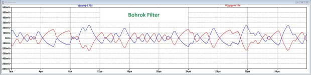
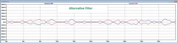
Looking at the signal directly on the two nodes of the eight 3k01 Firdac resistors (resp. pos and neg), three different filters where compared:
1) Marcel's filter starts with two 8.2nF caps.
2) Bohroks filter starts also with two 8.2nF caps, but has an added 1nF between the pos and neg Firdac ouputs
3) The Alternate filter, based on Bohrok's design, has two 10nF caps instead of 8.2nF and 10nF has been added between the two Firdac outlets replacing the 1nF in version 2).
When looking at the attached images, the original filter has the sharpest edges, Bohrok's filter has smoothened the curve a bit and the Alternative filter does even more passive filtering.
Since the idea is that more passive filtering before going active with op-amps, the alternative filter could be a step in that direction.
Hans
Attachments
Would you care to share the kicad files, thy would be way easier to look at - at least for me with kicad already installed.Made yet another version of Marcel's dac board, This one only differs in having added u.fl test points for clock and data signals going into the shift registers, test points for things like scope grounds, and test points for both Vref supplies. The test points can be used to monitor existing signals, or else used to inject external signals if some upstream resistors are removed first. Also, Marcel has reviewed the Gerbers and said they look okay.
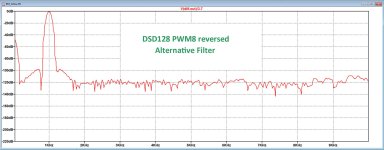
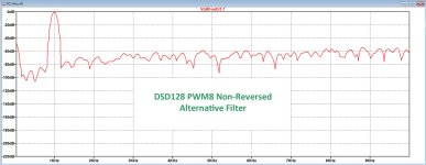
With a DSD128 .dsf file, prepared by Marcel with PWM8 , I have made the simulation with reversed and non reversed bytes.
It must be obvious that, given the much higher noise level, bytes will have to be reversed.
Time step was 0.5nsec and the Alternative Filter was used to get the lowest possible contamination from the Firdac's
Hans
It must be obvious that, given the much higher noise level, bytes will have to be reversed.
Time step was 0.5nsec and the Alternative Filter was used to get the lowest possible contamination from the Firdac's
Hans
Attachments
I could do that. However, Kicad 8 doesn't import fully from Marcel's old version of KiCad. Therefore some footprint libraries are missing, and some traces not on the correct nets. It all works anyway because the PCB and schematic files are still intact from what Marcel created. However, if you run the rule checkering in KiCad then it turns up a lot of errors and warnings. From looking through them they don't constitute real problems, but they may add a lot of clutter if you try to change things and you need to separate out the trivial warnings and errors from real ones you just created.Would you care to share the kicad files, thy would be way easier to look at - at least for me with kicad already installed.
What really needs to happen is someone needs go in and fix all the missing information in the form of footprints and trace net assignments.
The safest thing to do for now may be to look at the gerbers in KiCad's gerber viewer.
In the meantime a schematic with the test points shown is attached (test points are shown on sheets 2 and 3).
Attachments
Last edited:
- Home
- Source & Line
- Digital Line Level
- Return-to-zero shift register FIRDAC