As I mentioned in post #2180 I have already tried OPA1612 instead of OPA2210 in "stock" filter. It did not improve distortions at 10k. It seems to have same internal structure as OPAx210 but slightly higher quiescent current (3.6mA).
Probably more current in the input stage. Getting ~1nV|/Hz noise in a differential and low tail current will not agree. To get the 6dB improvement in noise over OPAx210 likely needs ~12dB more current. Given that the OPAx210 draws 2.2mA we can roughly figure out the IPS current in OPAx210 as ~0.5mA and in OPA1612 as ~2mA. So the OPS runs likely at less than 1mA quiescent.
My conclusions of my tests are that passive filtering before first op amp stage is important
This has been my experience with all DS/Hybrid DAC structures.
I will stick with OPA1632
It should be pointed out that OPA1632 also uses essentially the IPS as OPA1612/x210, so we can probably more or less exclude the IPS as source of the increased distortion.
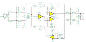
Lastly, the circuit I suggested is essentially a hybrid of a Jung compound Op-Amp with loop gain restoration (which also enhances output slew rate) and the Birt Circuit with common mode DC only servo.
You select the output OPA for high speed and hefty outputs, you select the input OPA for DC and AC behaviour required. You set second stage gain to restore the loop gain lost (
Using TPA6120/THS6012 in the output is of course overkill. But as Gen Joseph J. Nazzaro once remarked after an Arclight mission out of U-Tapao took out a square mile of jungle and a handful of VC's, no Charlie ever complained about having been overkilled. Other CFB OPA's with less output current will likely be just as good.
BUT, using THS6012 allows this circuit for line out:
This circuit is "decompensated" by adding gain after the first OPA in the compound, so it is similar to a "decompensated" OPA which is usually a good idea for I/U conversion.
88 Ohm Z-Out for balanced is acceptable even in studio context. Filter is comparable to the original 3-stage daisy-chain.
With a small LC filter with at east 1uH planar PCB Coil it can also direct drive a Headphone, though gain needs to come up for that.
This simplified compound/passive output has nearly 2dB advantage on SNR in the sim and reduces the effective circuit to one single fully differential stage with a single dominant NFB loop.
Of course, the OPA1632 is no slouch and can probably be used the same way, just output current is a little weedy for headphones and the passive filter on the line out may strain it.
Thor
Attachments
R6 should be 1K and for a flat response C3 should be 2nF.Probably more current in the input stage. Getting ~1nV|/Hz noise in a differential and low tail current will not agree. To get the 6dB improvement in noise over OPAx210 likely needs ~12dB more current. Given that the OPAx210 draws 2.2mA we can roughly figure out the IPS current in OPAx210 as ~0.5mA and in OPA1612 as ~2mA. So the OPS runs likely at less than 1mA quiescent.
This has been my experience with all DS/Hybrid DAC structures.
It should be pointed out that OPA1632 also uses essentially the IPS as OPA1612/x210, so we can probably more or less exclude the IPS as source of the increased distortion.
Lastly, the circuit I suggested is essentially a hybrid of a Jung compound Op-Amp with loop gain restoration (which also enhances output slew rate) and the Birt Circuit with common mode DC only servo.
You select the output OPA for high speed and hefty outputs, you select the input OPA for DC and AC behaviour required. You set second stage gain to restore the loop gain lost (
Using TPA6120/THS6012 in the output is of course overkill. But as Gen Joseph J. Nazzaro once remarked after an Arclight mission out of U-Tapao took out a square mile of jungle and a handful of VC's, no Charlie ever complained about having been overkilled. Other CFB OPA's with less output current will likely be just as good.
BUT, using THS6012 allows this circuit for line out:
View attachment 1290449
This circuit is "decompensated" by adding gain after the first OPA in the compound, so it is similar to a "decompensated" OPA which is usually a good idea for I/U conversion.
88 Ohm Z-Out for balanced is acceptable even in studio context. Filter is comparable to the original 3-stage daisy-chain.
With a small LC filter with at east 1uH planar PCB Coil it can also direct drive a Headphone, though gain needs to come up for that.
This simplified compound/passive output has nearly 2dB advantage on SNR in the sim and reduces the effective circuit to one single fully differential stage with a single dominant NFB loop.
Of course, the OPA1632 is no slouch and can probably be used the same way, just output current is a little weedy for headphones and the passive filter on the line out may strain it.
Thor
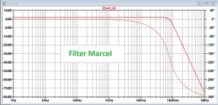
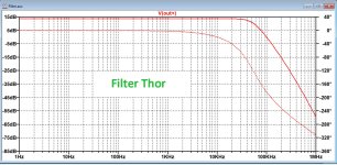
Filter has a lower order as Marcel's filter and has it's -3dB is at 52kHz.
See Marcel's filter to compare FR.
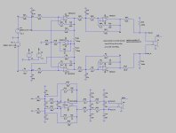
U1, U2 and U3 could be replaced by just one OPA1632.
Hans
Attachments
My apologies, I could have come to a wrong conclusion in the sim in the above posting.
R6 could probably remain at 270R but in my case it made the amp oscillate at 25kHz where 1K resulted in a stable system.
The shown frequency responses however are correct and so is C3 that has to be 2nF for a flat response.
Hans
R6 could probably remain at 270R but in my case it made the amp oscillate at 25kHz where 1K resulted in a stable system.
The shown frequency responses however are correct and so is C3 that has to be 2nF for a flat response.
Hans
Last edited:
It should be pointed out that OPA1632 also uses essentially the IPS as OPA1612/x210, so we can probably more or less exclude the IPS as source of the increased distortion.
Not necessarily. The peak voltage across the input stage and hence its distortion in those peaks depends on the open-loop output impedance. Whether there is only one differential pair or two that are more or less but not quite in series could also make a difference.
Last edited:
R6 should be 1K
Nope, it should not.
and for a flat response C3 should be 2nF.
I aimed for similar 100k & 10MHz attenuation. It is trivial to tweak the response of the filter for a specific target. Again, I am not trying to present a proven circuit to copy, but principles to be applied by those "skilled in the art".
The 10nF for C3 are retained in the interest of maximising the attenuation of HF noise at the differential input. Having the two inputs linked by 10nF and having 500 Ohm differential mode series impedance create a 5uS pole or a ~32kHz lowpass. That's 50dB attenuation at 10MHz. Use 2nF and it's 37dB.
Filter has a lower order as Marcel's filter
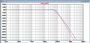
No, it has not. It has a different Q at the cut-off and a slightly different cut-off point final slope is the same:
U1, U2 and U3 could be replaced by just one OPA1632.
All OPA's could be replaced by one OPA1632. There are however reasons why the more complex circuit may be a better choice, as there are those why just a single OPA1632 per channel may be.
My apologies, I could have come to a wrong conclusion in the sim in the above posting.
R6 could probably remain at 270R but in my case it made the amp oscillate at 25kHz where 1K resulted in a stable system.
Did you use a current source as equivalent of the DAC, or a voltage source in series with resistors (which is what the DAC really is)? A CCS causes very different noise gain and will impact stability.
Thor
Not necessarily. The peak voltage at the input stage and hence its distortion depends on the open-loop output impedance.
Well, the open loop output impedance is determined by output stage design. Chicken and egg.
If high OL Zout causes the IPS to distort, whereas low OL Zout avoids this, it seems more reasonable to state that the increase in distortion is caused by the output stage.
The same IPS shows increased distortion with one output stage but not another, the solution is to fix the output stage, as realistically, we cannot fix the IPS.
Thor
With the given component values, I had a 2dB peak at 37.5kHz, also see attachment.I aimed for similar 100k & 10MHz attenuation. It is trivial to tweak the response of the filter for a specific target. Again, I am not trying to present a proven circuit to copy, but principles to be applied by those "skilled in the art".
The easiest way to flatten the FR was to reduce C3 from 10nF to 2nF, but this reduced the BW slightly.
I agree there are more sophisticated ways to flatten the FR.
You probably meant 1Mhz instead of 10Mhz.The 10nF for C3 are retained in the interest of maximizing the attenuation of HF noise at the differential input. Having the two inputs linked by 10nF and having 500 Ohm differential mode series impedance create a 5uS pole or a ~32kHz lowpass. That's 50dB attenuation at 10MHz. Use 2nF and it's 37dB.
In LTSpice the difference isn't that large, -47dB with 2nF and -53dB with 10nF.
I have put both filters on top of each other with Marcel's filter in red.No, it has not. It has a different Q at the cut-off and a slightly different cut-off point final slope is the same:
Marcel's filter is maximally flat.
This image was made with C3 at 10nF.
Bohrak's OPA1632 version, followed by two separate opamps seems the most sophisticated version so far.
The Firdac must be seen as a voltage source driving a compound resistor value of 376.25R, so in this very case IMO we have no I/V conversion.Did you use a current source as equivalent of the DAC, or a voltage source in series with resistors (which is what the DAC really is)? A CCS causes very different noise gain and will impact stability.
The eight shiftregister's output resistances probably add very little to this 376.25R.
Output voltage when producing 55H or "silence" is Vref x 0.25 = 1.125Volt (not 2.75Volt).
Hans
Attachments
With the given component values, I had a 2dB peak at 37.5kHz, also see attachment.
You use a different simulator from what I use, likely with different device models. You do not show the circuit you simulate. Sorry, but under such conditions it is hard to reconcile things when results differ.
It is important to remember that simulators are significantly limited in how closely they approach reality.
You probably meant 1Mhz instead of 10Mhz.
No. In our DAC using DS as operating principle (ideal DAC presumed) will have two distinctive sets of "digital" noise sources.
1) Noise shaping from the DS process. (DS noise from here)
2) Noise generally at harmonics and the fundamental of the DAC's update frequency (Switching noise from here)
Other noise may originate from non-ideal behaviour of the DAC, the most concerning being jitter.
The DAC's switching frequency is at appx. 12MHz (DSD256) or higher.
In LTSpice the difference isn't that large, -47dB with 2nF and -53dB with 10nF.
I calculated in my head strictly the amount of attenuation open loop from a first order filter of 500R/10nF vs. 500R/2nF. The difference must be a five times shift corner frequency and thus 5 times (15dB) less attenuation at the frequency of interest (10MHz).
My experience with switchercad has been that simulations show poor congruence with reality. It is one of the reasons I do not use it.
Bohrak's OPA1632 version, followed by two separate opamps seems the most sophisticated version so far.
I am not what "sophisticated" intends to imply. Which performance metric does it map to?
The Firdac must be seen as a voltage source driving a compound resistor value of 376.25R, so in this very case IMO we have no I/V conversion.
I agree on it being a voltage source in series with a resistance. I used 375 Ohm, an inconsequential difference.
The eight shiftregister's output resistances probably add very little to this 376.25R.
Around 35 Ohm, so if we want to be persnickety for fox's sake, the correct resistance would be approximately 380 Ohm, I do not think that resultant changes to the simulation results
Output voltage when producing 55H or "silence" is Vref x 0.25 = 1.125Volt (not 2.75Volt).
This is a netlabel I did not change from a different project where the discrete FIR DAC is supplied by 5.5V and midpoint is 2.75V.
As Vref is 4.975V (+/- 1% or so) the design center DC is 1.24375V and the differential signal (assuming Out = 0dBDSD = +6dBFS) is 2.4875V P-P.
I am unsure that being this precise in a simulation has any value. However, to avoid more pointless debate, have updated my model for the DAC as signal source as follows:
I will rerun the sim's later using this and make sure go back to Marcel's original filter design and make sure to curve match his filter precisely, not that this particularly matters, except for arguments sake.
Thor
Ok, first stop, Marcels original filter with a slightly simplified output buffer (for all practical points they are the same):

I shall use this circuit as the "holy curve" that must not not be deviated from (except perhaps having better attenuation above 1MHz. Other results...
Differential output is only 2V @ 0V DSD, 6dB below standard for PCM.
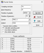
Unweighted SNR comes in at 116.5dB 20Hz-20kHz unweighed.
Simming THD with OPA's is largely pointless (models invariably show too much simplification to correlate to reality), I get around 0.0003%, if I allow enough settling time (1000mS sampling start time, 65k window and RMS).
Do we agree that this is our "reference"?
Thor
I shall use this circuit as the "holy curve" that must not not be deviated from (except perhaps having better attenuation above 1MHz. Other results...
Differential output is only 2V @ 0V DSD, 6dB below standard for PCM.
Unweighted SNR comes in at 116.5dB 20Hz-20kHz unweighed.
Simming THD with OPA's is largely pointless (models invariably show too much simplification to correlate to reality), I get around 0.0003%, if I allow enough settling time (1000mS sampling start time, 65k window and RMS).
Do we agree that this is our "reference"?
Thor
Ok, next comparison, circuit "Marcel original" vs. persenickity and pointless simulator finetuned ultra simple OPA1632.

Filter FR difference 20-20k is 0.06dB. I think we can call that sufficiently identical.

Next 10-100k, I call that a match:

1k-10M, the simple circuit has 10dB less attenuation at 1MHz compared to Marcel's filter, however if one looks at 10Mhz the simple circuit pulls ahead, in part because of the passive nature:

Now, let's look at a few other metrics that may, or may not impact things more than Filter slope.
Error at the "virtual earth" nulling point input tells us how much errors change with frequency.

The much lower loop gain of OPA1632 shows up at lower frequencies, however despite this most Audio range show 6dB advantage to "simple", with almost 9dB advantage at frequencies above 100kHz.
Next the actual OPA input pins:

Again, the limited loop gain of OPA1632 is clearly visible, however after the traces cross at 2kHz we see progressively less error, noise and distortion passing to the OPA Pins, at 200kHz the advantage is ~10dB (if you need to ask why the numbers are not adding to 10dB, think it through).
Noise, unweighted 20-20k next:

Advantage "Simple" by almost 3dB.
HD, I am seeing a problem with the TINA-TI's simulation engine. despite two separate circuits present, the engine reports almost identical HD. I guess I should file a bug report. Both show 0.004% with very similar distribution per harmonic. If I run separate instances and files Marcel's original sits at 0.0003% THD while OPA1632 simulates to 0.0009% I have zero confidence in either number.
Now, lastly, does the "simple compound" circuit do better? Yes. In what areas. Simulate yourself.
Thor
Filter FR difference 20-20k is 0.06dB. I think we can call that sufficiently identical.
Next 10-100k, I call that a match:
1k-10M, the simple circuit has 10dB less attenuation at 1MHz compared to Marcel's filter, however if one looks at 10Mhz the simple circuit pulls ahead, in part because of the passive nature:
Now, let's look at a few other metrics that may, or may not impact things more than Filter slope.
Error at the "virtual earth" nulling point input tells us how much errors change with frequency.
The much lower loop gain of OPA1632 shows up at lower frequencies, however despite this most Audio range show 6dB advantage to "simple", with almost 9dB advantage at frequencies above 100kHz.
Next the actual OPA input pins:
Again, the limited loop gain of OPA1632 is clearly visible, however after the traces cross at 2kHz we see progressively less error, noise and distortion passing to the OPA Pins, at 200kHz the advantage is ~10dB (if you need to ask why the numbers are not adding to 10dB, think it through).
Noise, unweighted 20-20k next:
Advantage "Simple" by almost 3dB.
HD, I am seeing a problem with the TINA-TI's simulation engine. despite two separate circuits present, the engine reports almost identical HD. I guess I should file a bug report. Both show 0.004% with very similar distribution per harmonic. If I run separate instances and files Marcel's original sits at 0.0003% THD while OPA1632 simulates to 0.0009% I have zero confidence in either number.
Now, lastly, does the "simple compound" circuit do better? Yes. In what areas. Simulate yourself.
Thor
Attachments

On the OPA1612 vs. 1632 IPS, the datasheet equivalent schematics indicate they are not the same... Both use LTPs, but the 1632 pair feeds a folded cascode terminating into current sinks in parallel with the OPS input, while the 1612 LTP sees a current mirror load in parallel with the VAS input. Not sure on the compensation for the 1632, but the 1612 has multiple caps loading the IPS, including one enclosing the OPS. These schematics may be leaving out additional cascodes or fancy current mirrors, but the basics are there, and the large difference in OLG bears them out. 1632 has 5pF less differential input capacitance.
Attachments
I'm puzzled why our simulations differ from each other.Ok, next comparison, circuit "Marcel original" vs. persenickity and pointless simulator finetuned ultra simple OPA1632.
View attachment 1290873
Filter FR difference 20-20k is 0.06dB. I think we can call that sufficiently identical.
View attachment 1290874
Next 10-100k, I call that a match:
View attachment 1290875
1k-10M, the simple circuit has 10dB less attenuation at 1MHz compared to Marcel's filter, however if one looks at 10Mhz the simple circuit pulls ahead, in part because of the passive nature:
View attachment 1290878
Now, let's look at a few other metrics that may, or may not impact things more than Filter slope.
Error at the "virtual earth" nulling point input tells us how much errors change with frequency.
View attachment 1290883
The much lower loop gain of OPA1632 shows up at lower frequencies, however despite this most Audio range show 6dB advantage to "simple", with almost 9dB advantage at frequencies above 100kHz.
Next the actual OPA input pins:
View attachment 1290884
Again, the limited loop gain of OPA1632 is clearly visible, however after the traces cross at 2kHz we see progressively less error, noise and distortion passing to the OPA Pins, at 200kHz the advantage is ~10dB (if you need to ask why the numbers are not adding to 10dB, think it through).
Noise, unweighted 20-20k next:
View attachment 1290885
Advantage "Simple" by almost 3dB.
HD, I am seeing a problem with the TINA-TI's simulation engine. despite two separate circuits present, the engine reports almost identical HD. I guess I should file a bug report. Both show 0.004% with very similar distribution per harmonic. If I run separate instances and files Marcel's original sits at 0.0003% THD while OPA1632 simulates to 0.0009% I have zero confidence in either number.
Now, lastly, does the "simple compound" circuit do better? Yes. In what areas. Simulate yourself.
Thor
Marcel's filter is the same in both our cases, but the -1dB points are at resp. 67.5kHz and 39.8kHz and at 100Khz curves are even 12dB apart for this OPA1632 Filter.
I have attached the circuit diagrams To me we have exactly the same circuitry, but don't think that it's worth to spend any more time on this issue.
I noticed a 4.5dB weighted lower input noise for the OPA1632 Filter, but CMRR was worse.
But because of component tolerances this difference will be nihilated.
Last point I wanted to mention is the looking at virtual input signals in your posting.
It seems that you regard this as distortion
But distortion to me is THD and not the slight amplitude error because of a finite open loop gain, because that's what you showed, the inverse of the open loop gain.
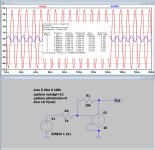
To clarify what I mean, look at the second attachment, pretending to be an amp with a limited gain of 10.
When trying to let this amp amplify the input signal by R1/R2, we don't get the wanted 20dB gain, so we have an obvious gain error.
Looking at the "virtual input" a signal is visible in blue at 1/10 of the output signal, 1/10 being the inverse of the open loop gain.
But when looking at the output signal's FFT there is zero THD.
So all I want to say, a signal at an amp's virtual input, does not automatically mean THD, which is more or less what your images tried to suggest to me.
Hans
Attachments

On the OPA1612 vs. 1632 IPS, the datasheet equivalent schematics indicate they are not the same...
I never said they where. They have the same input stages (NPN BJT Differential) something they share with OPAx210, while OPA1662 uses a PNP differential input.
Both use LTPs, but the 1632 pair feeds a folded cascode terminating into current sinks in parallel with the OPS input, while the 1612 LTP sees a current mirror load in parallel with the VAS input. Not sure on the compensation for the 1632, but the 1612 has multiple caps loading the IPS, including one enclosing the OPS.
The feedback via compensation capacitors has a similar effect as cascoding.
In terms of resistance to EMI and avoidance of rectification effects of EMI etc. they are more similar and different.
Thor
I'm puzzled why our simulations differ from each other.
I'm not. I never got very different simulators to give the same answer.
When all the DIY guys got into switchercad (which what is LT spice is - it designed originally for dynamic transient simulations on SMPS) and I had to leave PSpice behind, I compared various free and freely available (k3yg3n/cr4ck) simulation tools and tried to match them to circuits I already had IRL as actual commercial products. I picked what came closest and also found it more usable and with better models for many parts I routinely use.
As Charles Mordechai said, in theory there is no difference between theory and practice. In practice....
I have attached the circuit diagrams To me we have exactly the same circuitry
We have not. I tuned the values from my first "quick cut" design. They are not the values you use and I hid them on purpose. I wanted to demonstrate that to anyone skilled in the arts, making a pretty close fit of filter curves is just a question of working it out.
And no, I do not plan on providing the values. My purpose is not to provide circuits for others to copy, but to illustrate alternative angles and techniques that may be employed, to solve seeming unsolvable or untractable problems.
Last point I wanted to mention is the looking at virtual input signals in your posting.
It seems that you regard this as distortion
No, I do not regard this as distortion IN ITSELF, but rather as indication of the circuits ability correct errors. With an "ideal" circuit the error would be exactly zero. From DC to light.
Any difference is applied across the two BE junctions and can cause distortion products through a number of mechanisms.
If we have a "standard" 7th order DSD modulator with near 20kHz noise free bandwidth that is scaled to DSD256 we have the DSDnoise starting to rise at 80kHz above the noise and reaching +6dB DSD at 1/2FS. And we have sub harmoniocs of the bitclock (switching noise) starting at 1/2FS or even lower.
The less error at high frequencies the less the amplitude of these noise products across the inputs. The less the amplitude of these noise sources, the less the amplitude of any products that can fold back into the audio band.
Excessively simplistic simulation/testing with simple idle pattern or simple test signals will not be very revealing of this, listening may be. I tried every PCM to DSD converter I could find to create DSD signals that would allow me such tests (I had an AP2 at hand back then) to find they signals would cause converters to crash, to produce empty files etc. I ran out of time and gave up.
But distortion to me is THD
I would not stage that THD is the sole possible, meaningful or relevant distortion metric (not root cause), in fact I would suggest it is the least meaningful or useful one. I suggest you try noise loading or multitone tests.
So all I want to say, a signal at an amp's virtual input, does not automatically mean THD, which is more or less what your images tried to suggest to me.
Why would me stating "Error at the "virtual earth" nulling point input tells us how much errors change with frequency" suggest THD? I know the difference between Error and THD. In addition, the error at the inverting input is not solely the inverse of the loop gain. And that is where it get's interesting.
Remember, wherever we have a "slow" signal processed with a "slow" Circuit and the presence of significant noise components at frequencies where the linearity of said circuit is degraded, we look at the possibility of IMD.
If the noise is ideal and purely chaotic, we see a rise in noise floor,
If, as common with DS Modulators among other, we deal with shaped noise that is potentially modulated by signal, we are looking at something very different.
Thor
Yeah. But a lot of people find it very hard to believe because they feel if such were true it would be well explained by Self and or Cordell, the authors of the bibles of audio. Or maybe it can happen in dacs but EMI/RFI rarely is a problem in amplifiers unless maybe they are picking up radio stations. IOW, people just don't seem to get it.
Probably the reason they don't get it is because HD FFT spurs are easy to interpret. There is also some published research on how such spurs affect perceptual SQ. OTOH, a shift in the noise floor and or a shift in spectral line noise skirt width looks small on an FFT. And there is no published research on human sensitivity to such effects. Thus many people feel it is justified to assume such effects are completely negligible.
And then people go right back to talking about THD and or THD+N numbers as though that's all there is a that matters.
Changing the subject a bit, referring to noise intermodulated with an audio signal as IMD may confuse people who are trained to think of IMD as exclusively the product of a signal passing through an unchanging curved transfer function. In that view HD and IME are exactly the same measurement of nonlinearity, and both are exclusively PSS.
Maybe its because people learn simplified models first, then come to believe the models are the reality. At that point unlearning what is wrong about that becomes very difficult.
Last edited:
Dear Thor,I'm not. I never got very different simulators to give the same answer.
When all the DIY guys got into switchercad (which what is LT spice is - it designed originally for dynamic transient simulations on SMPS) and I had to leave PSpice behind, I compared various free and freely available (k3yg3n/cr4ck) simulation tools and tried to match them to circuits I already had IRL as actual commercial products. I picked what came closest and also found it more usable and with better models for many parts I routinely use.
As Charles Mordechai said, in theory there is no difference between theory and practice. In practice....
We have not. I tuned the values from my first "quick cut" design. They are not the values you use and I hid them on purpose. I wanted to demonstrate that to anyone skilled in the arts, making a pretty close fit of filter curves is just a question of working it out.
And no, I do not plan on providing the values. My purpose is not to provide circuits for others to copy, but to illustrate alternative angles and techniques that may be employed, to solve seeming unsolvable or untractable problems.
No, I do not regard this as distortion IN ITSELF, but rather as indication of the circuits ability correct errors. With an "ideal" circuit the error would be exactly zero. From DC to light.
Any difference is applied across the two BE junctions and can cause distortion products through a number of mechanisms.
If we have a "standard" 7th order DSD modulator with near 20kHz noise free bandwidth that is scaled to DSD256 we have the DSDnoise starting to rise at 80kHz above the noise and reaching +6dB DSD at 1/2FS. And we have sub harmoniocs of the bitclock (switching noise) starting at 1/2FS or even lower.
The less error at high frequencies the less the amplitude of these noise products across the inputs. The less the amplitude of these noise sources, the less the amplitude of any products that can fold back into the audio band.
Excessively simplistic simulation/testing with simple idle pattern or simple test signals will not be very revealing of this, listening may be. I tried every PCM to DSD converter I could find to create DSD signals that would allow me such tests (I had an AP2 at hand back then) to find they signals would cause converters to crash, to produce empty files etc. I ran out of time and gave up.
I would not stage that THD is the sole possible, meaningful or relevant distortion metric (not root cause), in fact I would suggest it is the least meaningful or useful one. I suggest you try noise loading or multitone tests.
Why would me stating "Error at the "virtual earth" nulling point input tells us how much errors change with frequency" suggest THD? I know the difference between Error and THD. In addition, the error at the inverting input is not solely the inverse of the loop gain. And that is where it get's interesting.
Remember, wherever we have a "slow" signal processed with a "slow" Circuit and the presence of significant noise components at frequencies where the linearity of said circuit is degraded, we look at the possibility of IMD.
If the noise is ideal and purely chaotic, we see a rise in noise floor,
If, as common with DS Modulators among other, we deal with shaped noise that is potentially modulated by signal, we are looking at something very different.
Thor
As a matter of fact, I think that LTSpice is quite accurate in it's prediction of frequency responses.
But not telling the component values in your circuit diagram, shows that your previous component values were obviously not as spot on as mentioned.
Showing error images without mentioning the supposed background why you showed them, is just as incomplete as showing Firdac diagrams without mentioning the source as is showing circuit diagrams in a DiyAudio forum without disclosing the values.
I'm done.
Hans
Mark,Yeah. But a lot of people find it very hard to believe because they feel if such were true it would be well explained by Self and or Cordell, the authors of the bibles of audio. Or maybe it can happen in dacs but EMI/RFI rarely is a problem in amplifiers unless maybe they are picking up radio stations. IOW, people just don't seem to get it.
Probably the reason they don't get it is because HD FFT spurs are easy to interpret. There is also some published research on how such spurs affect perceptual SQ. OTOH, a shift in the noise floor and or a shift in spectral line noise skirt width looks small on an FFT. And there is no published research on human sensitivity to such effects. Thus many people feel it is justified to assume such effects are completely negligible.
And then people go right back to talking about THD and or THD+N numbers as though that's all there is a that matters.
Changing the subject a bit, referring to noise intermodulated with an audio signal as IMD may confuse people who are trained to think of IMD as exclusively the product of a signal passing through an unchanging curved transfer function. In that view HD and IME are exactly the same measurement of nonlinearity, and both are exclusively PSS.
Maybe its because people learn simplified models first, then come to believe the models are the reality. At that point unlearning what is wrong about that becomes very difficult.
As you well know, we couldn’t agree more.
THD tells very little about sound perception and so do many other things.
HF content from a (Fir)Dac may very well influence sound perception and so do cable reflections, capacitors, etc, etc.
But in the end its all trying and listening to find out what you prefer most.
But isn’t this all discussed in great length ?
Hans
Discussed, yes, in way. However we still end up looking at a lot more PSS FFTs summarized as THD and THD+N in this forum than any other consideration. Why? Even when some recent FFTs of the output stage were posted, in that moment, those distortion numbers felt more important than anything else. Did you feel it too?But isn’t this all discussed in great length ?
- Home
- Source & Line
- Digital Line Level
- Return-to-zero shift register FIRDAC