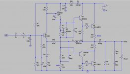
C3,C4 are intended to act as "sprog stoppers". So if you miss them out you will get sprogs. (high frequency oscillations). Whether you actually need both compared with one at twice the value is another question. C8 provides phase advance feedback to compensate the delays in the VAS loop.
Often this type of compensation scheme is discussed by others but they tend to describe the VAS stage loading with larger capacitors (1nF). The point is that the capacitors need to be reduced to the minimum necessary for stability, and as they do not get fed back into the base of the VAS they offer less roll-off and therefore more gain to reduced high frequency distortion - crossover in particular.
If you experience instability in one half (typically the lower where the PNP-NPN exhibit a double phase inversion) you can increase one capacitor as Andrew says by experiment.
If you want to restore the slew rate just increase the VAS current. Actually in all the simulations I have done nearly all VAS stages show less clipping on transients if the current is between 20 and 30 mA rather than the common 6mA.
John
Thanks for the additional explanation. Phase compensation design is over my head but I can detect oscillation when it occurs. I've installed the 50 pf b-e caps on the VAS stage of my ST120 included in the "TIP mod" by dynaco, when they went from 200 khz output transistors to 2 mhz ones about 1970.
The base dynaco ST120 I was planning to copy before I saw this has 20 ma feedback controlled output transistor idle current, by the djoffe 7 transistor mod proposed here: http://www.diyaudio.com/forums/solid-state/156627-dynaco-stereo-120-can-beautiful.html and built by me. This idle current is similar to what you specify. With 80 v rail my unit's transient response on top octave piano or bells/cymbals is excellent.
the NTE60 output transistors (MJ802 equiv?) seem to take that much idle current (20 ma) fine 15 hours per day, using fans on the inadequate dynaco heat sinks.
Per your comment on subsonics of simple amps, the ST120 single input transistor structure will pass subsonics, move the speaker cone, if I walk around the room with the magnetic phono cartridge down on the record and the subsonic filter turned off on the mixer, but doesn't seem to move the speaker cones around randomly on its own. The 3300 uf output caps of the ST120 imposes some sort of a lower limit on frequency. I see this design has 10000 uf output cap; that might allow more quasi-DC to leak through to the speaker. I'll stay with 3300 or 4700 uf output caps.
Last edited:
yes it is CFA!!! ") my first retro amp was from this post by mr mile (apexaudio) http://www.diyaudio.com/forums/solid-state/236256-retro-amp-50w-single-supply.html where i have posted two pcb layouts one for a modified version of the retro amp and one for a regulated psu.now i am going to build this one.
my first retro amp was from this post by mr mile (apexaudio) http://www.diyaudio.com/forums/solid-state/236256-retro-amp-50w-single-supply.html where i have posted two pcb layouts one for a modified version of the retro amp and one for a regulated psu.now i am going to build this one.
my first retro amp was from this post by mr mile (apexaudio) http://www.diyaudio.com/forums/solid-state/236256-retro-amp-50w-single-supply.html where i have posted two pcb layouts one for a modified version of the retro amp and one for a regulated psu.now i am going to build this one.Attachments

Last edited:
Thanks maouna for finding this and updating the inscrutable Xi and C5.
I have a collection of 3 channel organs (keyboard) with tube amps that could stand to lose 30 kg each, and I had been collecting parts to build dynaco ST120 clones, due to the speaker protection of the series capacitor. These later single supply schematics could be more competent.
I do understand why seventies single supply designs always use two NPN output transistors, since the 2n3055 then was half the price of pnp equivalents. Or for long there were no PNP equivalents. But why are these single supply designs invariably quasicomp output now? The price of pnp and npn is the same now.
tiefbassuebert & I have corresponded about this, and his proposal to "speaker protect w/o relais" doesn't in my limited understanding, include a series speaker capacitor that is always positive biased. ( Back to back electrolytic series speaker capacitors on split supply amps sound funny, by experiment).
Last edited:
I dont know how this circuit using modern transistors is going to perform when it comes to oscillation issues.. simulation results are very good however with no problems indicated.
These retro style amps have good harmonics distribution and i think this has also to do with quasi output stage topology used.
These retro style amps have good harmonics distribution and i think this has also to do with quasi output stage topology used.
Actual x00 khz Ft output transistors are long gone. The new 2n3055 etc are 2 mhz parts, mostly, if not faster. On Semi sn3772 is still allegedly quite slow Ft.
I've been coping with possible oscillation on the dynakit ST120 by putting 50 pf across driver b-e junctions as suggested by the dynaco "TIP mod". So far using NTE60 and NTE181MP output transistors, so good.
I think with the idle output bias current solved by modification, the ST120 sounds really good. So perhaps the quasicomp output has advantages of "proper" distortion. I really can't tell the difference in sound between ST120 and the fully complimentary Peavey CS800s, though.
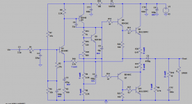
I made a layout for this amp...i hope the routing and ground distribution is fine..... some component values on the pcb layout are not correct and were choosen arbitrarily.. correct values are on the schematic.
some component values on the pcb layout are not correct and were choosen arbitrarily.. correct values are on the schematic.Attachments
Last edited:
- Status
- This old topic is closed. If you want to reopen this topic, contact a moderator using the "Report Post" button.
- Home
- Amplifiers
- Solid State
- Retro amplifier 50 watt circuit