Dear Russ,
I checked again all components and everything seems according to the schematic (would you like to send me a link to the last one with components value, just to be sure?).
I just didn't install C3 and C4, should be that the cause of the oscillation with R18 and R19 shorted?
As said: no input, no problem; if input R is below let's say 6-8 ohm (I tried also a resistor at the place of the cartridge), on the output I found DC (10-14volt!). With Input above 10Ohm, everything is OK and on the output I measure around 0.8mV offset.
What should I do? Do you need other info I can check (maybe with oscilloscope?).
Thx,
GM
Last edited:
Hi-Z with ortofon 2M
Hi
I have wired as Hi-Z that I am using with a ortofon 2M pickup into an ADC and then into the BuffaloDAC for volume control and then into Hypex UCD modules. I have a problem that the gain could have been a tad higher.
In addition the specifications for the pickup recommends a
-load resistanse of 47kOhm
-load capacitance of 150-300pF
How can I achieve this? (sorry if this is kind of a newbie question)
Hi all,
my experience on LOW Z: shorting R18 and R19 will result the circuit not working, I have a DC of about 10-14 volts on the output!
I just finished my Lo-Z Retro with R18 and R19 shorted and no C3/C4 and got exactly the same result on both boards. DC offset was <1mV and everything checked out fine using a 600 ohm output function generator as the input on my bench. I hooked it up to my system, and as soon as I turned the volume attenuator got a pop, and I knew I had DC. Sure enough, the DC offset at the output was ~14.5V (+/- 15V rails)! Fortunately my power amps have coupling caps!
However, I now remember that my turntable (Sony PS-X70) has auto-muting, which shorts the outputs with a relay until the tone arm lowers, so I had the input basically dead shorted. I can get rid of that relay (or actually just try with a record already playing) to add the cartridge resistance (Denon DL-103R) and see if it helps. The DL-103R is supposed to be 14R, so if 10 ohms is the threshold of stability, I may be OK, but would probably want a little more stability margin.
I'm actually quite glad to read that someone else has experienced the same thing and it's potentially not an error I made.
I changed R18/R19 from shorted to 15R8 since I knew I was going to need all the gain I could get and those were the only metal films I had on hand close to 20R. The circuit was perfectly stable on the bench with inputs shorted or open with this change. DC offset was reduced to <0.2mV. I thought I had the issue resolved. I then hooked it back into my system and found that one of the boards was once again oscillating when the input was shorted while the other was stable (perhaps due to temperature change?). It's stayed that way ever since, so I'm clearly on the edge of stability.
I haven't re-wired my turntable yet, so I'm using the factory RCA interconnects. I think before I make any more changes on the Retro board I'll re-wire the turntable interconnects to shielded twisted pair and XLR connectors and bypass the auto-muting relay to see how the circuit behaves with the cartridge load always present.
I did not spend any time probing the circuit to try and determine exactly why the instability is happening yet. However, I did listen to the one "good" channel and I'm going to need to add more gain through some other resistor adjustments too. As-is I had to rely quite a bit on preamp gain to get decent volume (estimate -14dB relative to CD level). This is why I did not simply switch the 15R8 resistors to the standard 100R ones quite yet.
I had a bit of audible 60Hz hum (non-balanced interconnects are not helping that), no audible 120Hz hum and the noise level was very acceptable, so I have little doubt I'll be able to get it working well eventually.
Russ:
Just found your forum today and have read all of it and enjoyed the back and forth in this forum. Thanks for educating phono preamp newbies like me about the challenges involved in building a differential phono preamp. Now, I applaud the use of a servo to eliminate DC on the output BUT why not simply tie Vcom of the output OPA1632 to ground directly as it'll do the same thing as the servo?
Also since you have input loads of 47K in the high-Z version per leg phase, doesn't that mean the cartridge will see a 94K impedance each for the left and right channels?
I realize these might be a stupid/naïve question so my apologies from the outset.
Thanks,
David
Last edited:
Well, the Retro is making me struggle.
I re-wired my turntable using shielded twisted pair microphone cable and XLR connectors, which was easier than I had expected. I decided to change R18/R19 to 50R to meet the minimum specified cartridge loading of 100R per the DL103R datasheet. I decreased R2 to 720R and R13 to 480R to increase the downstream gain.
One board works great. The other board continues to go unstable right to rail voltages with an input load less than ~300R. I also discovered that with no input connected, if I measure from ground to in- I get 72.X mV and from ground to in+ I get 37.X mV. Not good. On the good board I get -7.XmV for both measurements, with the direct measurement from in+ to in- being a few tenths of a mV. Measuring the outputs of IC2 yields similar voltages.
I have checked all resistors around IC2 for correct values and verified all is well. I have probed all around the circuit with an oscilloscope with the inputs shorted and can find no signs of oscillation anywhere up to 500MHz. I suspect the issue may not be oscillation, but instability in the servo circuit.
However, the very unbalanced voltages around IC2 leads me to suspect that IC2 has been damaged and needs to be replaced. The other interesting thing is that if I hook up a signal generator with 600R output impedance the circuit amplifies the signal fine, so the circuit is functional at some level.
Any other thoughts?
From the little bit of testing I have done, the good board sounds excellent, but it is rather hard to assess that with only one channel playing") . Noise (power supply and mains) performance is very good, and I know from past experience that is very non-trivial when trying to get ~70dB gain for low output MC cartridges.
. Noise (power supply and mains) performance is very good, and I know from past experience that is very non-trivial when trying to get ~70dB gain for low output MC cartridges.
I re-wired my turntable using shielded twisted pair microphone cable and XLR connectors, which was easier than I had expected. I decided to change R18/R19 to 50R to meet the minimum specified cartridge loading of 100R per the DL103R datasheet. I decreased R2 to 720R and R13 to 480R to increase the downstream gain.
One board works great. The other board continues to go unstable right to rail voltages with an input load less than ~300R. I also discovered that with no input connected, if I measure from ground to in- I get 72.X mV and from ground to in+ I get 37.X mV. Not good. On the good board I get -7.XmV for both measurements, with the direct measurement from in+ to in- being a few tenths of a mV. Measuring the outputs of IC2 yields similar voltages.
I have checked all resistors around IC2 for correct values and verified all is well. I have probed all around the circuit with an oscilloscope with the inputs shorted and can find no signs of oscillation anywhere up to 500MHz. I suspect the issue may not be oscillation, but instability in the servo circuit.
However, the very unbalanced voltages around IC2 leads me to suspect that IC2 has been damaged and needs to be replaced. The other interesting thing is that if I hook up a signal generator with 600R output impedance the circuit amplifies the signal fine, so the circuit is functional at some level.
Any other thoughts?
From the little bit of testing I have done, the good board sounds excellent, but it is rather hard to assess that with only one channel playing
. Noise (power supply and mains) performance is very good, and I know from past experience that is very non-trivial when trying to get ~70dB gain for low output MC cartridges.Just as a follow up, I finally replaced IC2 (OPA1632). As I suspected, that completely fixed the instability problem. This was the first time I had ever worked with SMD components, but I was pleasantly surprised at how easy it was to change the IC using Chip Quik.
Using the resistor configuration I mentioned above is about perfect for the DL-103R cartridge, about 70dB gain. Retro is an exceptionally quiet phono stage, and is certainly the best that I have owned or built. Thank you for making this design available Russ!
Using the resistor configuration I mentioned above is about perfect for the DL-103R cartridge, about 70dB gain. Retro is an exceptionally quiet phono stage, and is certainly the best that I have owned or built. Thank you for making this design available Russ!
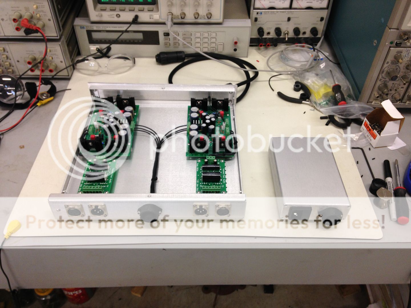
Turbotoy,
Thanks for posting the picture. A very nice and clean build. May I ask, what power supply are you using?
Thank you very much! The power supplies are the AMB [FONT=arial,helvetica][SIZE=-1]σ22[/SIZE][/FONT]. I used them mostly because I had a lot of spare parts lying around from building others for other projects, and I have found the performance to be excellent. Using two in a dual mono configuration is certainly overkill in some respects, but it does get rid of one ground loop. Each power supply has its own dedicated transformer in the separate enclosure. When trying to get 70dB of active gain, I wanted to do everything I could to minimize noise/hum.
This was the first time I had ever worked with SMD components, but I was pleasantly surprised at how easy it was to change the IC using Chip Quik.
Nice looking! Wonder if you could explain Chip Quik, as I am not familiar with it?
Thanks
Nice looking! Wonder if you could explain Chip Quik, as I am not familiar with it?
Chip Quik is an alloy with a low melting point that mixes well with solder. The idea is to "flood" the existing solder joints with Chip Quick, which then mixes with the existing solder. Because of the low melting point, you can heat one side of the chip then heat the other, and still have time to remove the chip before the solder freezes. No worries about lifting pads, etc.
Hi! I got a slight problem to deal with: I have a small background (grounding issue)noise.
The turntable is balanced connected with Retro input: just + and -, then Retro connected +, -, and ground to balanced connectors and to my preamplifier. I hear ground noise, also when I touch the arm of the turntable it is quite sensitive and I hear clicks.
What is the grounding scheme that should be applied to get rid of it?
Regards, zz
Hi! I got a slight problem to deal with: I have a small background (grounding issue)noise.
The turntable is balanced connected with Retro input: just + and -, then Retro connected +, -, and ground to balanced connectors and to my preamplifier. I hear ground noise, also when I touch the arm of the turntable it is quite sensitive and I hear clicks.
What is the grounding scheme that should be applied to get rid of it?
Regards, zz
First, double-check that there is no connection between -OUT or +OUT from your cartridge and the chassis of the turntable.
If that's okay and you still have noise, you can connect the chassis of the turntable to Earth Ground (Mains ground). It should have no connection to the signal, so this should not cause any issues.
- Home
- More Vendors...
- Twisted Pear
- Retro - A fully symetrical phono stage with RIAA filter