Crown has the service manual available for download here:
http://www.crownaudio.com/pdf/legacy/dc300asm.pdf
dave
http://www.crownaudio.com/pdf/legacy/dc300asm.pdf
dave
New thread
Yes we will meet, it is inevitable. I have some New Threads! Thanks for the Gucci Jacket Chris!
anatech said:Hi Shawn...your time will come and we shall meet, you and I! Bah, ha ha ha ha.
This is an excellent new thread, I can split it out if you wish. PM me if that is the case.
-Chris")
Yes we will meet, it is inevitable. I have some New Threads! Thanks for the Gucci Jacket Chris!
Attachments
anatech said:Hi Quasi,
Now I guess you will just have to pick one of these up!
-Chris
Ha...sorry guys...just had to go get a tissue. A Quasi-complementary..oh no here I go again.....

anatech said:Hi Quasi,
You do realise that all solid state devices are actually Quasi - conductors.
Quick, get this man a box of tissues and a bucket!
-Chris
Bwaaaaarrrrrgh arrrgh haaaargh ....stop it please.
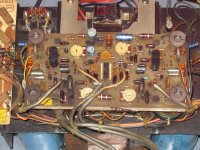
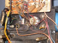
Ok I'm off to do the transistor substitution analysis. Sorry Shawn but by the looks of the photo of the input and driver board, I would replace everything....xept the inductors (why the .....have they got inductors?)
Cheers
Q
Re: Thanks for the mail guys.
You've got me smiling and feeling like I was a little kid again. And Thanks (Dave) planet10, the schematic has been free on the Crown site for many years. So everybody go get a copy of this old (who said "beasty") and play along.
The OpAmp on the preDriver boards says:
F739PC
7511
(would that be 1975 date code?)
It is 14 pin dip, how nice, it has a socket! There is an OpAmp pin out and internal diagram inside the PDF from Crown. This amp is almost as old as me!!!!
Shawn (Tom Waits) in 1974. How cute is that? Pure terror, just ask my Ma? He he he.
I just realised this, its weird and way off topic but my great Uncle whom I greatly admired (RIP) is the pic in my Avatar and he is the person behind the camera of the little Shawn picture. Furthermore the Avatar is circa 1975. Funny but nice.
quasi said:...and to find that it's a Quasi-complementary.....well I'm starting to.....sniff...I gotta go now...sniff.
anatech said:Hi Quasi, Now I guess you will just have to pick one of these up! Chris
You've got me smiling and feeling like I was a little kid again. And Thanks (Dave) planet10, the schematic has been free on the Crown site for many years. So everybody go get a copy of this old (who said "beasty") and play along.
The OpAmp on the preDriver boards says:
F739PC
7511
(would that be 1975 date code?)
It is 14 pin dip, how nice, it has a socket! There is an OpAmp pin out and internal diagram inside the PDF from Crown. This amp is almost as old as me!!!!
Shawn (Tom Waits) in 1974. How cute is that? Pure terror, just ask my Ma? He he he.
I just realised this, its weird and way off topic but my great Uncle whom I greatly admired (RIP) is the pic in my Avatar and he is the person behind the camera of the little Shawn picture. Furthermore the Avatar is circa 1975. Funny but nice.
Attachments

Hi Shawn,
Yep, it's 1975, 11th week. It is not a normal op amp either, but you could adapt one. They still have some of these original ICs hiding around, but they are dear. Be careful with the one you have.
A PCB rework using new components may be the pinacle of performance for this amplifier.
-Chris
Yep, it's 1975, 11th week. It is not a normal op amp either, but you could adapt one. They still have some of these original ICs hiding around, but they are dear. Be careful with the one you have.
A PCB rework using new components may be the pinacle of performance for this amplifier.
That would be me.(who said "beasty")
-Chris
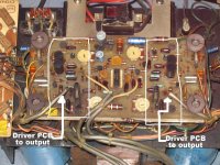
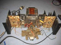
I remember this design. The 739/749 series from Fairchild were kinda weird first generation low noise opamps with a common emitter output stage (?!!). If I remember correctly, the 749 had an open collector output. With some jiggery-pokery, these could be used as the front end for a power amp. Why anyone would bother these days is beyond me. There is enough room to ditch the input board and build something decent like a fully complementary lineup a la Leach. If the output devices are original, I would ditch them as well, as better things have been available for years. When I look at the rust on the power transformer and see all the open carbon pots on the driver board, I cringe. The amp was lucky to survive.
anatech said:A PCB rework using new components may be the pinacle of performance for this amplifier. That would be me.
-Chris
This is what I would want to strive for by keeping the essence but upgrading where possible. Could be a pipe dream because...
wrenchone said:...There is enough room to ditch the input board and build something decent like a fully complementary lineup a la Leach. If the output devices are original, I would ditch them as well, as better things have been available for years. When I look at the rust on the power transformer and see all the open carbon pots on the driver board, I cringe. The amp was lucky to survive.
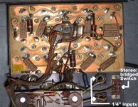
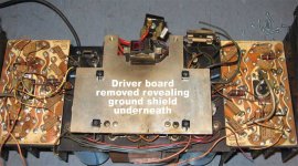
because I kinda agree here too Wrench. I'm very worried about the output devices. Come on, the PN junctions have got to wear down and start leaking? But that is a little too soon as I will test them to make certain. The XFMR was sitting directly on a wet cement floor for 1 or two 2 years; I think it stood up well. The amp has been serviced, you can see in post #37 on the low left a brand new resistor and transistor. The areas I marked with the white box in post #37 have serious heat damage on the surface of the components. This driver stage had little and almost no heat sink to dissipate and it shows. However, this can be rectified.
Attachments
- Home
- Amplifiers
- Solid State
- Resurrecting a Crown DC300A