This is probably a little off the trend but about the original finish and what I think it might actually be.
My hunch is that the original coating came from an aircraft paints catalog. Think epoxy primers and exteriors.... circa 1958. Very tough finish.
re: powder coating pale blue slightly translucent. Nice idea.
-Steve
Hmmn. Not that they were as tough, but a lot of late 50's-era automotive colors come to mind too. Certainly there are a lot of "era-accurate" colors that would work. Did a search and here's a snappy color (snappy car too).
http://www.corvetteblogger.com/images/content/020110_1.jpg
and a couple on this one look like good matches.
1958 Chevrolet All Models Colors of Touch Up Paint
Great observations Steve.
I think the original designers would have chosen some form of Delrin had it been available. I too got mine from McMaster Carr. The smallest quantity was a strip 1" wide 5' long .04"thick for 3.90 USD. That's enough for 85 or more thrust pads. I've no excuse for reusing pads. I just hold the original pad to the new material and cut around it with scissors. It doesn't have to be perfect. Once assembled the pad shouldn't move.
I've completely dissembled both of my TT's (SN's 2045 and 85982). I;m fascinated by the many small differences between the two. Regarding the spindle bearing: The older spindle has a loose ball while the newer's ball is captured. The older bearing well has a flat end cap with a 1mm thick gasket. The newer well has an offset dish shaped end cap and has a much thinner .2mm gasket.
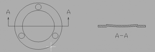
Newer end cap drawing:
Here is a photo of the top of original nylon thrust plates, left 2045, right 85982:
Bottom:
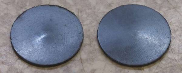
I got both TT's used so I can't speak for the much larger wear dimple in the older plate but notice, the older plate secured with a flat end cap and thick gasket has a donut like ring around the dimple that is .1mm higher than the edge. The distance from the top of the ring to the bottom of the dimple is .28mm. The newer plate shows no raised ring but a cone shaped slope of .2mm from the edge to the bottom of the dimple.
From this geometry the newer would likely show a smaller dimple with the same amount of use, but I doubt this was the designers concern. The well wall is thin providing precious little meat around the end cap retaining screws for the gasket to seal against. I suspect they pressed the raised profile in the newer end cap to strengthen it and force the gasket to deform around the raised portion providing a better seal. Then they dished the raised portion so the center would be level with the edge placing the bearing itself as the older flat cap did. However this required a thinner gasket.
I think the original designers would have chosen some form of Delrin had it been available. I too got mine from McMaster Carr. The smallest quantity was a strip 1" wide 5' long .04"thick for 3.90 USD. That's enough for 85 or more thrust pads. I've no excuse for reusing pads. I just hold the original pad to the new material and cut around it with scissors. It doesn't have to be perfect. Once assembled the pad shouldn't move.
I've completely dissembled both of my TT's (SN's 2045 and 85982). I;m fascinated by the many small differences between the two. Regarding the spindle bearing: The older spindle has a loose ball while the newer's ball is captured. The older bearing well has a flat end cap with a 1mm thick gasket. The newer well has an offset dish shaped end cap and has a much thinner .2mm gasket.
Newer end cap drawing:
Here is a photo of the top of original nylon thrust plates, left 2045, right 85982:
Bottom:
I got both TT's used so I can't speak for the much larger wear dimple in the older plate but notice, the older plate secured with a flat end cap and thick gasket has a donut like ring around the dimple that is .1mm higher than the edge. The distance from the top of the ring to the bottom of the dimple is .28mm. The newer plate shows no raised ring but a cone shaped slope of .2mm from the edge to the bottom of the dimple.
From this geometry the newer would likely show a smaller dimple with the same amount of use, but I doubt this was the designers concern. The well wall is thin providing precious little meat around the end cap retaining screws for the gasket to seal against. I suspect they pressed the raised profile in the newer end cap to strengthen it and force the gasket to deform around the raised portion providing a better seal. Then they dished the raised portion so the center would be level with the edge placing the bearing itself as the older flat cap did. However this required a thinner gasket.
OT Comments about Arms, Cartridges, Pre-amps used with my TD-124s
The set ups the two arms reside in are so different it is impossible to make an entirely fair comparison. My TD-124/II is a rather quieter / more perfected machine overall than the TD-124/I that the SME clone resides on.
There is really no question at all that the Schick is a better arm, better damped, better bearings, better overall precision. Better sound.
The cartridge on the Schick is the top of the line Royal N SPU which is a substantially better cartridge than the Meister Silver which it replaced within hours of getting here somewhere around 18 months ago.
The Muscovite phono pre used with the 124/II / Schick / Royal N is several notches up the design and performance ladder from the Muscovite Mini II used with the 124/I / clone / Meister Silver, and there is 12 feet of interconnect between the phono and the line stage.
There are a number of issues with the 124/I relating to that POS zamac platter and the motor mounts which let a lot of motor noise through.
The 3012 clone is pleasant enough, but I suspect not exactly neutral, nor the last word in resonance free - the Meister does not shine quite the same way it does on the Schick. I would say it was money well spent given that it cost 1/3 what the Schick cost, and performs reasonably well. This arm seems to perform similarly to the stock 3012 but perhaps not quite as well. I think this arm has some HF colorations that could be damped with the addition of a little balsa in the arm tube. It is also quite possible that it is just revealing the considerable remaining warts in this TD-124. (Not to mention possibly that some of the bad things I hear could be the new phono stage which is a work in progress)
I can't really give a fair assessment of the clone arm on this TT, but I can say that the Schick was head and shoulders better than a restored SME 3012 Series II in a direct comparison around the time I first got the Schick and on the MKII table.
The second table set up is primarily what I use to develop new phono pre-amp designs so that I do not have to disturb the primary set up which serves as my reference.
Edit: Just switched to the reference set up, there is absolutely no comparison unfortunately.
Further investigation reveals that the MKII set up is cleaner sounding with the Mini, but the fundamental issue moved with the pre-amp. So more work is required.
Hello Kevin,
Could you post some pictures of your clone 12" SME tone arm and give a mini review/comparison with your Other arms?
Thanks,
David
The set ups the two arms reside in are so different it is impossible to make an entirely fair comparison. My TD-124/II is a rather quieter / more perfected machine overall than the TD-124/I that the SME clone resides on.
There is really no question at all that the Schick is a better arm, better damped, better bearings, better overall precision. Better sound.
The cartridge on the Schick is the top of the line Royal N SPU which is a substantially better cartridge than the Meister Silver which it replaced within hours of getting here somewhere around 18 months ago.
The Muscovite phono pre used with the 124/II / Schick / Royal N is several notches up the design and performance ladder from the Muscovite Mini II used with the 124/I / clone / Meister Silver, and there is 12 feet of interconnect between the phono and the line stage.
There are a number of issues with the 124/I relating to that POS zamac platter and the motor mounts which let a lot of motor noise through.
The 3012 clone is pleasant enough, but I suspect not exactly neutral, nor the last word in resonance free - the Meister does not shine quite the same way it does on the Schick. I would say it was money well spent given that it cost 1/3 what the Schick cost, and performs reasonably well. This arm seems to perform similarly to the stock 3012 but perhaps not quite as well. I think this arm has some HF colorations that could be damped with the addition of a little balsa in the arm tube. It is also quite possible that it is just revealing the considerable remaining warts in this TD-124. (Not to mention possibly that some of the bad things I hear could be the new phono stage which is a work in progress)
I can't really give a fair assessment of the clone arm on this TT, but I can say that the Schick was head and shoulders better than a restored SME 3012 Series II in a direct comparison around the time I first got the Schick and on the MKII table.
The second table set up is primarily what I use to develop new phono pre-amp designs so that I do not have to disturb the primary set up which serves as my reference.
Edit: Just switched to the reference set up, there is absolutely no comparison unfortunately.
Further investigation reveals that the MKII set up is cleaner sounding with the Mini, but the fundamental issue moved with the pre-amp. So more work is required.
Attachments
Great observations Steve.
I think the original designers would have chosen some form of Delrin had it been available. I too got mine from McMaster Carr. The smallest quantity was a strip 1" wide 5' long .04"thick for 3.90 USD. That's enough for 85 or more thrust pads. I've no excuse for reusing pads. I just hold the original pad to the new material and cut around it with scissors. It doesn't have to be perfect. Once assembled the pad shouldn't move.
I've completely dissembled both of my TT's (SN's 2045 and 85982). I;m fascinated by the many small differences between the two. Regarding the spindle bearing: The older spindle has a loose ball while the newer's ball is captured. The older bearing well has a flat end cap with a 1mm thick gasket. The newer well has an offset dish shaped end cap and has a much thinner .2mm gasket.
Newer end cap drawing:
Here is a photo of the top of original nylon thrust plates, left 2045, right 85982:
Bottom:
I got both TT's used so I can't speak for the much larger wear dimple in the older plate but notice, the older plate secured with a flat end cap and thick gasket has a donut like ring around the dimple that is .1mm higher than the edge. The distance from the top of the ring to the bottom of the dimple is .28mm. The newer plate shows no raised ring but a cone shaped slope of .2mm from the edge to the bottom of the dimple.
From this geometry the newer would likely show a smaller dimple with the same amount of use, but I doubt this was the designers concern. The well wall is thin providing precious little meat around the end cap retaining screws for the gasket to seal against. I suspect they pressed the raised profile in the newer end cap to strengthen it and force the gasket to deform around the raised portion providing a better seal. Then they dished the raised portion so the center would be level with the edge placing the bearing itself as the older flat cap did. However this required a thinner gasket.
The photos tell the story well. The "flexy" end cap that the Thorens designer went with. On the examples I have there is always a slight outward dome shape to it. This may come after the turntable has some use. In the case of excessive and damaging vertical motion, (hammering) the flexy cap may become excessively dome shaped
Fwiw all of my TD124 players are of the original series (mk1) and serial numbers are not high. The raised interior of the cap is designed to force the gasket into direct contact with the internal chamfer at the end of the bearing housing bore. With some care at assembly, and care during platter assembly, it is possible to create a liquid tight seal at this point. but it is also fairly easy to have a seat where some oil seeps out the bottom of the cap.
One of the first things I did was to produce a massive rigid end cap.

With this fitted it is possible I may get a slightly different coast-down behavior than I would with the standard cap fitted. The flexy cap will certainly allow the thrust pad to flex and bend along with it. I thought it preferable to have absolute rigidity at the thrust point.
but then I haven't done any -snr- testing between the two bearing caps, so there may be more for me to understand.
-Steve
The cap really makes a huge difference IMO, I have a bronze one on the MKII, and stainless steel on the MKI.. Both run mild steel thrust plates and oem steel balls which ultimately I will replace with silicon nitride balls. IIRC the correct diameter is 8mm.
The TD124 main bearing uses a 6mm ball. this size is easy to source in very hard steels and in tungsten carbide. Somehow it is not so easy to find in si ni ceramic. the ceramic balls are readily available in .250 inch size. Which is .35mm larger in dia. than the 6mm balls. One might be able to live with that.
-Steve
I've got a pile of different sized ball bearings, apparently the silicon nitride ones I have are 7mm when I checked. I also have 6mm steel and 5mm steel for various other uses..
There are plenty of silicon nitride bearings on eBay in metric sizes from Hong Kong where I got my last batch.
eBay item: 39059040525
Looks like I will need to get some of the proper size. No rush.
There are plenty of silicon nitride bearings on eBay in metric sizes from Hong Kong where I got my last batch.
eBay item: 39059040525
Looks like I will need to get some of the proper size. No rush.
Boca Bearings - Search Results for 6mm ball gr 5
6,6MM-C SI3N4 GR.5 BALLS (EA.),Metric, Balls
if you only need one, Boca has these.
I was taking a survey of the ebay ceramic balls. Chinese made. I still have "issues" with buying stuff made in China....except for when I want it.
I'd be ticked to find out that the Boca 6mm ceramic ball was also sourced from China. sigh.
-Steve
I need more than one unfortunately, and the Boca price isn't really competitive once that is true. The PN appears to be the same as the one mentioned by a number of eBay sellers so I suspect the ball bearing is probably made in China in any case. I generally shop on price + shipping charges and seller rating in order to stretch my limited funds.
Fwiw all of my TD124 players are of the original series (mk1) and serial numbers are not high. The raised interior of the cap is designed to force the gasket into direct contact with the internal chamfer at the end of the bearing housing bore.
Interesting. Thorens must have changed the end cap design early in production. #2045 had an absolutely flat end plate and a thick 1mm gasket. #85982 had a stamped cap and thin .2mm gasket.
Thrust bearing parts top. Left #2045, right #85982:

Bottom:

I'm convinced that the dome shape is intentional. They may have domed it to lower the bearing point after having raised it when they pressed in the shoulder to get a better seal. However, they may have done it to reduce the dimple formed by wear. Notice in the above top photo the thick gasket compresses under between the well wall and the end cap forming a sealing shoulder. In the original design, the ball would compress the thrust plate and the thick gasket. This causes the area around the ball contact point to rise. This rise would tend to "hug" the ball increasing contact area and thus accelerating wear and increasing friction. In the new design the thin gasket would compress far less and the dome shape stretches the thrust plate and reduces the ball hug dynamic.On the examples I have there is always a slight outward dome shape to it. This may come after the turntable has some use. In the case of excessive and damaging vertical motion, (hammering) the flexy cap may become excessively dome shaped
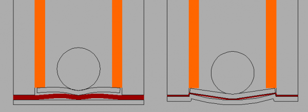
Old and new thrust bearing design (curvatures exaggerated for clarity):
As did I. It just made sense to me. I didn't know if it has sonic advantages but I was sure it'd make a better seal.One of the first things I did was to produce a massive rigid end cap.
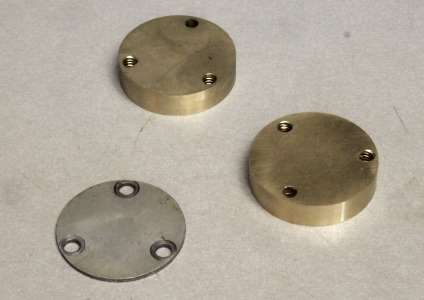
I'd seen thick end caps on-line. I was sure the vaulted gunmetal choice was hogwash and the outside chamfer which demanded counterbored screws were superfluous, so I just cut mine out of 1/4" flat brass. At this time #85982 was in storage so I didn't know about the formed end cap and so had no reason to turn a shoulder on the end cap.
Unless you dished the raised portion You've actually raised the bearing point. I believe the dish is integral to the designers' intention. The thin gasket is essential to this design. As I said, I made my end caps before I knew about formed end cap I just bought plain old gasket material to match my original. Now I think I should rethink my choice. The stuff I used doesn't come as thin as .2mm. What do you guys use?The internal shape duplicates the raised dimension of the original Thorens flexy cap.
Last edited:
One observation: forcing the thrust pad into a concave shape will create a larger contact patch between ball and pad in comparison to a configuration that allows the pad to lie flat. I don't consider the concave shape at the thrust to have any benefit. Optimum config would be to have a flat pad with only a very slight dimple from initial wear-in. The dimple would assist the bearing ball/shaft to maintain its central axis. But the smaller the dimple, the better.
An externally hosted image should be here but it was not working when we last tested it.
I hadn't seen a flat end cap before your post. The ones I have seen are like the end cap on the right side of the above photo. thanks for showing that.
re: end cap shape and platter height. True, the raised section, if cupped or not cupped, will alter platter height by some amount. And this will make it necessary to adjust the three conical clutch pins to compensate for the difference. Same thing happens if you use a thicker or thinner thrust pad material.
re: gasket materials.
original Thorens.....very thin .006 inches and easily torn. Can be ruptured by the hydraulic pressure of inserting the platter/shaft into the housing when enough oil is present. (and all of the Schopper Thorens people in the know will say to not do that. Rather, they say, install the end cap with thrust pad/gasket after the bearing shaft has been installed into the housing and they will also recommend removing the three machine screws that secure the iron platter to the shaft, remove the platter and store elsewhere during transit. ) I got these gems of advise from a former NA Schopper distributer.
I've been using automotive gasket material. heavy oiled paper. (brown) Tough stuff. .023 inches thick. It seems to be re-useable. Does not rupture from hydraulic pressures.
note: differences in gasket material thickness will not alter platter height.
-Steve
I've seen both types, and in the case of my tables have received aftermarket end caps that were flat and I deliberately machined one to make it flat and the proper thickness to work properly with my thin mild steel thrust plates.
I use the same sort of gasket material as Steve, and for safe measure I apply a very small amount of automotive RTV to the bottom of the housing and the end cap and spread it around. Make sure it goes nowhere else. Even with an inch or so of 30wt oil in the bottom of the housing I have never had a blow out.
I use the same sort of gasket material as Steve, and for safe measure I apply a very small amount of automotive RTV to the bottom of the housing and the end cap and spread it around. Make sure it goes nowhere else. Even with an inch or so of 30wt oil in the bottom of the housing I have never had a blow out.
Thanks guys on the info about gasket material. I think the thin gasket is essential to the original designers' rethinking of the bearing.
I know it's counter-intuitive but the dished end cap design actually leads to a smaller contact area than the original flat one.
Bottom:
On the left with the flat plate it looks like the ball was placed in the hole of a donut. The dished design on the right has exhibits a shallow straight sided cone shape. It's do to cold flow in the thrust pad. The flat cap forces the nylon to flow up around the ball but the dish puts the pad under tension limiting cold flow to stretching. However, as you can see in the bottom photo the pronounced pimple on the back of the original design pad is partially due to it sinking into the soft thick gasket.
This is all angels dancing on the head of a pin territory. Using a thin gasket and the tougher Durlin pad should lead to excellent results regardless of whether the cap is flat or dished. I'm ceremonially not going to bother to dish mine.
All this leads me to puzzle: Why did they make the bearing well wall so thin. The thin wall leaves very little gasket contact area. Even with small 3mm screws there is less than 1mm between the screw hole and the well wall edge. Every thing else in the machine is oversize and conservative in design. It can't be cost savings. The well is cast iron, cheap, easy to machine and doesn't require a fine finish. I think the fault lies in interdepartmental issues at Thorens. The chassis designers provided a 28mm hole for the spindle assembly. Perhaps at the time they were planning to use a 10mm spindle. Anyway, it was decided that the TD 124 should have a 14mm spindle. The chassis guys having spent thousands on the die-cast mold were unwilling to change the hole size. You may notice that very little was changed on the chassis over the production lifetime. The biggest obvious difference is the added flange on the center armboard support. Since adding the flange only required milling material out of the mold it was easy to accomplish. Making the hole bigger would require adding material to the mold which is much more difficult. It might even have meant scrapping the existing mold. Anyway, what is left is a sub-optimal design, very un-Thorens like.
new coils from simone Lucchetti, follow-up
5/1/2014....I've had a couple of days to listen to 13943 using the new motor windings. Here are some observations about the operation and sound quality of the deck...

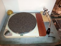
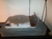
Above photo: 13943 on the rack. Plinth in use is for temporary utility. Tonearm: Zeta. Cartridge: DL103R SS ruby/FL and in a Uwe Panzerholz body.
13943 is in an open box plywood plinth, on the rack and playing records. No mushrooms. I've taken no measurements. When it comes to determining any increase/decrease in motor power or torque I can only note how quickly it starts up from cold, how well it maintains pace and what if any changes I hear to sound quality. During the motor assembly process and then the bushing/shaft alignment-tuning process I did notice that the motor did not vibrate quite so much as before with the older coils. This is a subjective observation based on holding the motor in hand while it runs. And also listening to the casing with a stethoscope as it runs. It does seem quieter.
From a cold start 13943 takes a couple of platter revolutions before the strobe indicates arrival at speed. When it does hit steady at 33-1/3rd rpm, it almost seems to snap in. Then, right after that episode the strobe indicates a slight amount of slowing over the next few minutes as it becomes finally steady. A few minutes only. It seems to hold speed throughout the day without any significant deviation from nominal.
Listening. It sounds just like a healthy TD124. Nice snap-to rhythm lines. It has a good sense of pace that seems rock steady. Nice open detailed and large sound fields. I've been listening to rock, classical and jazz so far.
Heat. It does run warm with the new replacement coils. Not burn-your-fingers warm,.....but warm.
Anytime we start talking about how warm these motors run I have to consider just how much of an effect operating heat has on two aspects of motor performance;
1) speed consistency throughout the listening session
2) long term motor life.
I think I gathered from reading through the translation of Simone' pages that he linked windings heat to motor rpm. Too much heat affects rpm in a negative way. Or did I read something that wasn't there? If I didn't, then it might seem as the coils get hotter, hotter than they should be, speed consistency will suffer.
Simone did mention that he uses a slightly larger magnet wire-gage-size and attempts to place a bit more "air" between each wind to help control temperature. This brings up something I'd like to suggest later, but...later.*
re: wire gage. In what way does magnet wire gage size in a motor coil determine power and torque of the motor? larger gage size must indicate greater capacitance. Greater capacitance and greater resistance means.....what in a motor? Torque and power, I'm guessing. Need to find a good primer on electric motor design.
re: cooked windings and motor performance. Older motors with windings that have been running too hot for too many years lose power. It may explain why some of these old girls take so long to get up to speed. Cooked windings.....maybe.
* re: the "later" comment.
The Thorens design allows operation at three different voltage levels. 250/200, 150/130, 125/100. A coil for each range. I wonder if that much capability isn't just a bit more redundancy than is really needed. What if someone wound some coils just to operate at one voltage range. Say...100-125. And only that. That should leave much more room in the core for some additional space between each wind. Hmmm, such a motor should run much cooler, don't ya think.
-Steve
preface. I thought that reporting on the reproduction mkII e50 windings from Simone Lucchetti would be appropriate to this thread. So here's the follow-up to the assembly process noted in the above quote.
The new coils arrived yesterday via registered mail. Exactly two weeks from ship date. That's fair time coming from Europe, btw.
More photos:

Above photo: the old and the new side by side. The new coils are a bit larger in dimension and will fit tighter into the core.

I followed Simone's instruction pdf and took care to dress off any sharp edges in the core parts where the coils come into physical contact with the core. I used a small fine cut file in combination with 400-grit sand paper to very slightly round the once sharp edges.


Once the motor was assembled the next task was to install into the TD124 chassis, then solder the leads coming from the coils onto the voltage terminal of the Td124. This coil set duplicates the windings of the original E50 and offers operation at 3 voltages just like the original. I used a photo taken of the AC terminal from another TD124 as a map for soldering .
Everything went without a hitch. I'm now spinning records.
other notes: I have not found it necessary to adjust the eddy magnet/ pulley gap distance.
I'll operate the player this way for a couple of days, watching closely, and then write down more observations to the page at my site where I'm making notes of my sn 13943 project.
13943
So far so good.
-Steve
5/1/2014....I've had a couple of days to listen to 13943 using the new motor windings. Here are some observations about the operation and sound quality of the deck...
Above photo: 13943 on the rack. Plinth in use is for temporary utility. Tonearm: Zeta. Cartridge: DL103R SS ruby/FL and in a Uwe Panzerholz body.
13943 is in an open box plywood plinth, on the rack and playing records. No mushrooms. I've taken no measurements. When it comes to determining any increase/decrease in motor power or torque I can only note how quickly it starts up from cold, how well it maintains pace and what if any changes I hear to sound quality. During the motor assembly process and then the bushing/shaft alignment-tuning process I did notice that the motor did not vibrate quite so much as before with the older coils. This is a subjective observation based on holding the motor in hand while it runs. And also listening to the casing with a stethoscope as it runs. It does seem quieter.
From a cold start 13943 takes a couple of platter revolutions before the strobe indicates arrival at speed. When it does hit steady at 33-1/3rd rpm, it almost seems to snap in. Then, right after that episode the strobe indicates a slight amount of slowing over the next few minutes as it becomes finally steady. A few minutes only. It seems to hold speed throughout the day without any significant deviation from nominal.
Listening. It sounds just like a healthy TD124. Nice snap-to rhythm lines. It has a good sense of pace that seems rock steady. Nice open detailed and large sound fields. I've been listening to rock, classical and jazz so far.
Heat. It does run warm with the new replacement coils. Not burn-your-fingers warm,.....but warm.
Anytime we start talking about how warm these motors run I have to consider just how much of an effect operating heat has on two aspects of motor performance;
1) speed consistency throughout the listening session
2) long term motor life.
I think I gathered from reading through the translation of Simone' pages that he linked windings heat to motor rpm. Too much heat affects rpm in a negative way. Or did I read something that wasn't there? If I didn't, then it might seem as the coils get hotter, hotter than they should be, speed consistency will suffer.
Simone did mention that he uses a slightly larger magnet wire-gage-size and attempts to place a bit more "air" between each wind to help control temperature. This brings up something I'd like to suggest later, but...later.*
re: wire gage. In what way does magnet wire gage size in a motor coil determine power and torque of the motor? larger gage size must indicate greater capacitance. Greater capacitance and greater resistance means.....what in a motor? Torque and power, I'm guessing. Need to find a good primer on electric motor design.
re: cooked windings and motor performance. Older motors with windings that have been running too hot for too many years lose power. It may explain why some of these old girls take so long to get up to speed. Cooked windings.....maybe.
* re: the "later" comment.
The Thorens design allows operation at three different voltage levels. 250/200, 150/130, 125/100. A coil for each range. I wonder if that much capability isn't just a bit more redundancy than is really needed. What if someone wound some coils just to operate at one voltage range. Say...100-125. And only that. That should leave much more room in the core for some additional space between each wind. Hmmm, such a motor should run much cooler, don't ya think.
-Steve
Last edited:
Wow, Simone makes a nice looking coil, and the finished motor looks brand new. Was the original cooked, or just very tired?
Yes indeed, heaver wire means less resistance. More energy goes into moving the rotor, less into heat.
It looks like there are two coils that are tapped at 2 places. I think these coils are in series and the "switch board" connects the correct taps. If I'm right, the 220V taps use the entire coil and so are maximally efficient, the lower voltages, not so much. Had they only supported 120 and 220 volts they could have used 4 separate coils that could have been wired in series or parallel so both would use all the wire.
Last edited:
Wow, Simone makes a nice looking coil, and the finished motor looks brand new. Was the original cooked, or just very tired?
The original to 13943 had one dead coil. Three of the 4 leads coming from it were shorted. And the coil on the other side of the core seemed to be ok. I bought it (13943) that way as a "fixer-upper". I've got the good coil in the photo for comparison against Simone's coils. The dead original coil from 13943 I have partially dissected. Perhaps I can learn something from it.
Yes indeed, heaver wire means less resistance. More energy goes into moving the rotor, less into heat.
I had thought something to that effect. Except, until now, I've been perfectly happy to remain ignorant about electric motor theory. Now, I've got a reading list.
what I understand so far: larger gage wire means lower impedance + then add higher current to get More torque
It looks like there are two coils that are tapped at 2 places. I think these coils are in series and the "switch board" connects the correct taps. If I'm right, the 220V taps use the entire coil and so are maximally efficient, the lower voltages, not so much. Had they only supported 120 and 220 volts they could have used 4 separate coils that could have been wired in series or parallel so both would use all the wire.
I was thinking something to the effect that a single voltage coil system could allow the use of an optimal wire gage size for this application. Except I don't know how much torque/power would be too much. Or, to say it another way, at what power level motor vibration becomes too great.
I do think that the other mechanical drive train elements are, for the most part, simple to deal with on a TD124. It is the motor that really poses the greatest impediment to realizing the true design goals of this machine. And, I suspect, the key component within this motor seems to be the coil systems. the rest of it is easy to maintain.
-Steve
There was a variant of the E50 made for the TD-121 which was designed solely for 117V/60Hz operation, I am not aware of any advantage in terms of its performance.
You do know that the individual windings on an E50 are just a tapped 100 - 125V coil and you can actually place the entire coil on each side in parallel if you wish to do so - just make sure the polarities are correct or you will fry the coils. (Use a 15 - 25W ballast lamp in series with the motor to protect the windings in the event you connect them wrong) The downside of doing this is that Thorens actually used the windings as an auto-transformer to step up 100 - 125, and 125 - 150V supplies to 200 - 250V for the neon lamp. Actual neon voltage depends on the supply voltage and tap chosen obviously, and some of the neon lamps that Thorens used will not light much below 190Vrms based on limited experience here.
I would be surprised if this made any difference at all to the performance of the motor. Resistive losses in the coils should be close to identical. These are not broadband audio transformers and we don't really care too much about leakage inductance in 60Hz induction motors..
There was a variant of the E50 made for the TD-121 which was designed solely for 117V/60Hz operation, I am not aware of any advantage in terms of its performance.
The TD111 is another example of an E50 with single voltage utility.
The point that maybe I didn't quite describe the way I meant is that a single voltage coil system would take less space in the core, and thus allow (make room for) the use of heavier gage magnet wire. We don't know that that was done with the motors on the TD111 or TD121. I'm guessing that the 111 and 121 motors were a cost cutting exercise. Ironically I did have a motor from a TD111 for a time. But I sold it to someone that had a TD111 in need of a motor, so there it went.
But.....with heavier wire...and more space between each wind, the motor should operate at a lower temperature than the E50s we know. It would produce greater torque as well. And I think that would result in greater speed consistency (cooler running). Quicker start-ups. Greater dynamics. Greater jump factor.
You do know that the individual windings on an E50 are just a tapped 100 - 125V coil and you can actually place the entire coil on each side in parallel if you wish to do so - just make sure the polarities are correct or you will fry the coils. (Use a 15 - 25W ballast lamp in series with the motor to protect the windings in the event you connect them wrong) The downside of doing this is that Thorens actually used the windings as an auto-transformer to step up 100 - 125, and 125 - 150V supplies to 200 - 250V for the neon lamp. Actual neon voltage depends on the supply voltage and tap chosen obviously, and some of the neon lamps that Thorens used will not light much below 190Vrms based on limited experience here.
I just purchased a couple of spare neon bulbs for my parts inventory. Part number #NE 48 (old# B9A) operates on 105 - 125 vac. Bayonette BA15d
I guess several different bulb mfr's used to make this type. the old number which can be used as a cross reference is B9A with a BA15d mount. The ones I bought are now made by CEC and have a glass bulb. Beware that there are others out there with plastic. My price was $4.95 each via ebay.
I would be surprised if this made any difference at all to the performance of the motor. Resistive losses in the coils should be close to identical. These are not broadband audio transformers and we don't really care too much about leakage inductance in 60Hz induction motors..
The idea of making the use of the entire coil isn't something that would occur to me. I could not speculate on the difference between doing that or just rewinding with a much larger wire gage. But with the small gage wire that's in there already, as densely packed as it is.....?
-Steve
Slightly off the coil topic which is very interesting, I was wondering if someone could tell me what the triangular plate on top of the motor is there for. I put my 124 into service the other day by mounting my Linn Ekos tonearm with a Grace F9e cartridge. I was just scavenging to put together a way to listen to the table before I start to restore it. I did oil and clean a bit and put on a nos belt. I was surprised to hear how well this is sounding. The motor comes up to speed and becomes pretty stable. This thread has been beyond helpful. Thanks to Steve and Kevin for sharing their hard won experience.-Robert
There was a variant of the E50 made for the TD-121 which was designed solely for 117V/60Hz operation, I am not aware of any advantage in terms of its performance.
You do know that the individual windings on an E50 are just a tapped 100 - 125V coil and you can actually place the entire coil on each side in parallel if you wish to do so - just make sure the polarities are correct or you will fry the coils. (Use a 15 - 25W ballast lamp in series with the motor to protect the windings in the event you connect them wrong) The downside of doing this is that Thorens actually used the windings as an auto-transformer to step up 100 - 125, and 125 - 150V supplies to 200 - 250V for the neon lamp. Actual neon voltage depends on the supply voltage and tap chosen obviously, and some of the neon lamps that Thorens used will not light much below 190Vrms based on limited experience here.
I would be surprised if this made any difference at all to the performance of the motor. Resistive losses in the coils should be close to identical. These are not broadband audio transformers and we don't really care too much about leakage inductance in 60Hz induction motors..
Kevin just back from hollidays interresting idea I shall do some measurements
these days concerning the vibration in the parallel 220 volt connection thus on 110 Volt against the normal series connection.
On the lenco forum they claim a improvement !!
Neon no problem you can get 110 Volt ones !
Volken
- Home
- Source & Line
- Analogue Source
- Restoring and Improving A Thorens TD-124 MKII