I built an kit pre-amp. Its very well designed transformer output but the mids are very cold. I'm not sure where to go to optimize this for a better mid tonality and weight.
A friend suggested changing the .1uF coupling cap with a .22 and dropping the grid resistor from a 1K to a 200 - 400R.
My voltages at the moment are:
Pin 1: 95VDC
Pin 3: 4 VDC
Pin 4/5: 11.75VDC
Pin 6: 13VDC
Pin 8: 5.9VDC
Pin 9: 258VDC
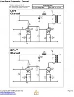
This is a copyrighted production circuit. Hopefully AN kit doesn't mind me showing it.
A friend suggested changing the .1uF coupling cap with a .22 and dropping the grid resistor from a 1K to a 200 - 400R.
My voltages at the moment are:
Pin 1: 95VDC
Pin 3: 4 VDC
Pin 4/5: 11.75VDC
Pin 6: 13VDC
Pin 8: 5.9VDC
Pin 9: 258VDC
This is a copyrighted production circuit. Hopefully AN kit doesn't mind me showing it.
Attachments
IMO, the absence of a grid stopper on the O/P triode is an error. As has been discussed, at several times and on several "boards", grid stoppers should be Carbon composition.
Before you change the value of any parts, please tell us what sort of coupling cap. is in situ now?
Before you change the value of any parts, please tell us what sort of coupling cap. is in situ now?
The power supply is a valve rectified ECL82 with a 6x5 output.
The .1 is an Audio Note Tin cap.
On the grid stopper - you mean after the coupling cap? As there is a grid stopper on the input.
Yes, I changed the metal film to carbon on the grid stoppers when I built it.
The OT is a 33:1
The .1 is an Audio Note Tin cap.
On the grid stopper - you mean after the coupling cap? As there is a grid stopper on the input.
Yes, I changed the metal film to carbon on the grid stoppers when I built it.
The OT is a 33:1
On the grid stopper - you mean after the coupling cap? As there is a grid stopper on the input.
The grid stopper should be as close to the tube pin as possible (here between C5 and the pin 7). Preferably soldered directly to pin 7.
What about the value of the stopper. I've been doing some searching and seeing more values like 300R instead of the 1K they use. Also all the others use a .22 C
Anyone know where I can find the schematic to Brett's 12B4?
What do you guys think about the voltages on the pins?
Anyone know where I can find the schematic to Brett's 12B4?
What do you guys think about the voltages on the pins?
On the grid stopper - you mean after the coupling cap? As there is a grid stopper on the input.
That's correct. The 5687 is a high gm type, which makes it especially vulnerable to parasitic oscillation.
Yes, I changed the metal film to carbon on the grid stoppers when I built it.
Carbon film or Carbon composition? Carbon film resistors are spiral trimmed, which makes them inductive. Only Carbon comp. is both non-metallic and non-inductive.
The .1 is an Audio Note Tin cap.
From what I've been able to determine, AN Tin foil caps. have a YUCKY polyester dielectric. Think about installing Soviet surplus PIO (paper in oil) parts.
BTW, the 6X5 is a full wave rectifier. That would leave the 6BM8/ECL82 performing regulator duties.
The M7 schematic can be found here.
http://www.diyparadise.com/simplepreamp.html
Is this kit an actual product of Audionote or some rip off oriental piece of crap?
In the past I built a copy of the Audionote 5687 line stage and was pleased with the result.
http://www.diyparadise.com/simplepreamp.html
Is this kit an actual product of Audionote or some rip off oriental piece of crap?
In the past I built a copy of the Audionote 5687 line stage and was pleased with the result.
I have been pondering the 33:1 step down. Why would anyone use such a transformer? Did AN recycle an output? ")
Seems like all their current kits come with ECL82 as regualtors - dacs and all. While previously even their phono stages used passive filtering. Weird. Must have had an excellent deal on the ECL82s.
Seems like all their current kits come with ECL82 as regualtors - dacs and all. While previously even their phono stages used passive filtering. Weird. Must have had an excellent deal on the ECL82s.
I put in a .22 and it sounds world's better. Moved it from cold and sterile to more dynamic and better weight and tonality.
I'm going to play with the grid stopper values today and see what that does. They seem to have standardized that power supply. Andy Grove likes the 33:1 output trans. Apparantly they use something like that in the production models. I don't know much about OT although I do know having the lowest DCR on the primary is good. This one is close to 600R
I'm going to play with the grid stopper values today and see what that does. They seem to have standardized that power supply. Andy Grove likes the 33:1 output trans. Apparantly they use something like that in the production models. I don't know much about OT although I do know having the lowest DCR on the primary is good. This one is close to 600R
I lowered the grid stopper to 220R (closest to 200R I had lying around). That helped separate the highs. Now I need to optimize it more. Its moving in the right direction.
Right now I'm running 95VDC 4mA on the 1st stage Plate with a bias of 4VDC 4mA.
Second stage bias is 13VDC 8.7mA with 258 on the plate
Any suggestion of what to shoot for?
Right now I'm running 95VDC 4mA on the 1st stage Plate with a bias of 4VDC 4mA.
Second stage bias is 13VDC 8.7mA with 258 on the plate
Any suggestion of what to shoot for?
Phrarod,
Since nobody seems to react about the voltages you measured: Yes, they appear to be in order.
But I have a great big puzzle. If replacing the 100nF coupling capacitor with a 220nF altered the sound significantly (and not questioning your experience), something must have been very wrong with that 100nF. The roll-off (-3dB point) with the 100nF was < 2 Hz! With the 220nF it has moved down to < 1Hz. That that could be audible is out of the question, unless something else was very wrong.
Yes, Audio Note .1uF/630 Tin to a ASC .22uF polystyrene. The ASC isn't a hi-end cap by any means. The difference is very noticeable. After that and the grid stopper reduction even my wife claimed it was a 100% improvement.
I'm clueless if you think it shouldn't have made that much of a difference. Electrically it appears correct and the power supply as well. I've been building circuits as a hobby for just 10 years so I could've done something wrong I just don't know what. I went over everything.
I'm clueless if you think it shouldn't have made that much of a difference. Electrically it appears correct and the power supply as well. I've been building circuits as a hobby for just 10 years so I could've done something wrong I just don't know what. I went over everything.
Yes, Audio Note .1uF/630 Tin to a ASC .22uF polystyrene. The ASC isn't a hi-end cap by any means. The difference is very noticeable.
The observation is not, in the least bit, surprising. AN uses Mylar (polyester) as the dielectric in their Tin capacitors. Polyester exhibits poor behavior in the dissipation factor and dielectric absorbtion depts. Also, polyester performance degrades with increasing freq. OTOH, polystyrene is 2nd only to PTFE in transparency. You switched guano out and something decent in. The "Catch 22" with polystyrene is heat vulnerability.
Be constantly alert for the Emperor's New Clothes Virus. Just because AN sells something does not make it "wonderful".

As the following remark is off-topic, I am leaving it only as such; not a topic to be pursued further.
The performance of the di-electric material in a capacitor is certainly of consequence, and has been the subject of much very meaningful research. But I often notice that in judging the performance of capacitors, track is lost of its actual role in a particular circuit. When in a frequency controlling circuit YES!! But a coupling capacitor is supposed to be a 'short' at audio frequencies. Ideally it neither charges nor discharges in the pass-band. The di-electric characteristics are therefore of secondary importance under such circumstances. It can only influence performance by way of electrical absorbtion, charge retention et al, when there is a voltage variation across it. Otherwise it acts as a 'fixed voltage drop' device.
It is also interesting that in his very exhaustive studies, Cyril Bateman in his landmark series on capacitor effects of some 7 years ago, found polyester capacitors to contribute lowest distortion as coupling capacitors.
As said, Phrarod, this is not a refutation of your observations - I was after all not there to be able to disagree!
Perhaps just my memory - I will dust off old research and refresh the grey cells (white by now).
Johan. No offense talken. I've been in audio my whole life. Most of my career I worked for the music studios as a commercial producer and was in the recording studios of all the major labels most days.
I've also been into audio since the 80's. Go to a lot of live concerts and still have some friends in the business. If I'm really stuck on something I have some recording engineers come over with their masters and they listen.
All any of us can do is listen. Doesn't matter what who said where. There are so many variables it all comes down to what sounds good to us in our systems. I'm sure you've been to people's home where they show off their system and you want to run away screaming.
All I can tell you is whether it was a value change or a materials change it made more of a difference than I was prepared for. According to the tube curve this circuit isn't within the sweet spot or even near it. I'm not adept at reading these curves so I could be wrong. I'll drop the loading resistor to 33K from 39K. If its a positive change I'll play with the bias resistors.
Anyone who can read a tube curve and comment I sure would appreciate it.
Dude,
If somebody knows where 5687 plate curves can be found, I'd like a link. This 5687 data sheet has a table of operating conditions on its last page.
If somebody knows where 5687 plate curves can be found, I'd like a link. This 5687 data sheet has a table of operating conditions on its last page.
- Status
- This old topic is closed. If you want to reopen this topic, contact a moderator using the "Report Post" button.
- Home
- Amplifiers
- Tubes / Valves
- Resolving cold midrange in 5687 circuit