As ususal I found a forum here and I thought it was parts
but I guess not. It had various results of measuring resistor
distortion. They were 1 ohm, 10 ohm, 100 ohm 1000 ohm?
Also, had power resistors as well.
But I can't find the thread nor forum nor link nor results from
searching for it either.
Anyone know where it is?
Anyone recall where the article is located?
The internet age is great but it is still "age"
and with that maturity comes forgetting where
one finds things.
Cheers,
Now where is that "Enter" button?
I know it is around here somewhere.
As ususal I found a forum here and I thought it was parts
but I guess not. It had various results of measuring resistor
distortion. They were 1 ohm, 10 ohm, 100 ohm 1000 ohm?
Also, had power resistors as well.
But I can't find the thread nor forum nor link nor results from
searching for it either.
Anyone know where it is?
Anyone recall where the article is located?
The internet age is great but it is still "age"
and with that maturity comes forgetting where
one finds things.
Cheers,
Now where is that "Enter" button?
I know it is around here somewhere.
Maybe it was Ed Simon's article in Linear Audio?
Jan
Anyone know where it is?
Anyone recall where the article is located?
The internet age is great but it is still "age"
and with that maturity comes forgetting where
one finds things.
Cheers,
Now where is that "Enter" button?
I know it is around here somewhere.
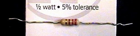
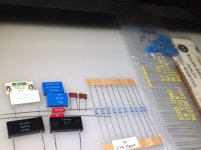
Found this one, any good ?

Mona
Attachments
I don't know, I read it here on DIYAudio, there may have been alink to
the article the guy wrote. I think he used 50 of each type of resistor
and did some very good research about it. He had multi colored plots
for the resistor types and brands used. All good stuff.
But I couldn't find it or reference when I tried to find it again.
I will look for simon7000s posts. Stay tuned.
I wanted to read it and then try some measurements
using the same procedure and see how a different variaty
of resistors measure up or down.
Cheers,
Sync
Thanks Mona,Found this one, any good ?
Mona
To what are you referring?
The squiggly wired thing?
OR
You found the ENTER button and something
came along for the ride?
Ho, ho, ho,
Sync
@ SyntcTronx
Not distortion but current noise in resistors types article imho is useful in your practic builds.
Thermal distortion are minimised if use of higher power range so resistors stay relatively cold.
https://dcc.ligo.org/public/0002/T0900200/001/current_noise.pdf
http://conradhoffman.com/papers_lib/TI_Noise_Prec_Resistors.pdf
Ohmite made resonable price cost WN serie Ayrton Perry type is worst to try
http://www.ohmite.com/cat/res_wh_wn.pdf
Best regards")
Not distortion but current noise in resistors types article imho is useful in your practic builds.
Thermal distortion are minimised if use of higher power range so resistors stay relatively cold.
https://dcc.ligo.org/public/0002/T0900200/001/current_noise.pdf
http://conradhoffman.com/papers_lib/TI_Noise_Prec_Resistors.pdf
Ohmite made resonable price cost WN serie Ayrton Perry type is worst to try
http://www.ohmite.com/cat/res_wh_wn.pdf
Best regards
Beat me to it, the LIGO guys laughed when I told them I knew about this study, I guess the guy that did it is quite a character talk about completeness. I think Gerhard translated all the colors to something intelligible.
Last edited:
Soundhappy, Scott:
Yes, that is the ONE. Thank you so much. I've been looking for it on and off
for weeks. And behind every door--was nothing. It is the Ligo study.
I tried to order the "little pink thin line" resistors and the distributor
hung up the phone on me.
Okay quiten time.
Yes, that is the ONE. Thank you so much. I've been looking for it on and off
for weeks. And behind every door--was nothing. It is the Ligo study.
I tried to order the "little pink thin line" resistors and the distributor
hung up the phone on me.
Okay quiten time.
Last edited:
All,
I am not yet convinced about the use of a bridge and an AP 2722 to measure sub PPM distortion.
The AP analyzer has a -118dB Residual Noise and the analog generator has a -112dB Residual THD + N. The reported distortion measurements are from the frequency domain.
So what are the parlor tricks used to report distortion below the reported capacity of the AP2722? The “DUT” is included in a bridge, the measurement is taken across the bridge; if there are equal levels of fundamental test frequency and distortion across the bridge there will be 0 Volts delta input to the analyzer. Add a high gain preamplifier at the analyzer input, low level signals are amplified to be within the dynamic range of the analyzer providing an apparent lowering of the analyzer noise floor and apparent increase of the sensitivity of the analyzer.
So what might be wrong with application of these techniques? For the bridge we are putting a lot of faith in perfect reference resistors and capacitors. At sub PPM levels perfect is not going to happen. For the analyzer with a added high gain preamplifier there will be spectral leakage in that less than perfect bridge, we will be measuring distortion leakage from the generator.
If we are going to speak of sub PPM distortion from resistors and capacitors we do not have the techniques or equipment to measure it.
About the importance of sub PPM distortion we need to be discussing it in the time domain. In the time domain we do not get 50 samples to average down noise in order to isolate distortion. In the time domain noise will completely consume sub PPM distortion.
DT
The Audio Precision resistor papers:
"From the Test Bench: Resistor noise and non-linearity"
https://www.ap.com/technical-library/from-the-test-bench-resistor-noise-and-non-linearity/
"From the Test Bench: Resistor noise and non-linearity"
https://www.ap.com/technical-library/from-the-test-bench-resistor-noise-and-non-linearity/
There is a 2012 IEC standard for testing resistor distortion. Attached is the draft standard, the official standard has a copyright. The test procedure does not use a bridge.
It would be interesting to see a comparison of the bridge test results and the results using the IEC Standard procedure.
Looking at Ed Simon’s bridge test results there is significant leakage of the test frequency. That leads me to think that there also may be leakage of harmonics from the generator at play as well.
DT
Attachments
I work on my diy class A Sony CSX1 amplifier from Mr Pass topology.
Short audio path only input Jensen transformer , 220 uFcap, 1K resistor and vfet transistor.
That half of push-pull mono power stage.
With luck and time maybe i can solder on rotary switch few resistors to compare
hope electronic science and audiophile pleasure meets together.
Verify some truth aspects from above articles ?
Need try miniature Ohmite WN wire wound serie as well.
Best regards
Attachments
I am not yet convinced about the use of a bridge and an AP 2722 to measure sub PPM distortion.
The AP analyzer has a -118dB Residual Noise and the analog generator has a -112dB Residual THD + N. The reported distortion measurements are from the frequency domain.
So what are the parlor tricks used to report distortion below the reported capacity of the AP2722? "DT
The "trick" is called an FFT. It relies upon the completely legitimate property of signals whereby stochastic signals (i.e. noise) do not behave the same way as deterministic signals (such as spurious distortion products and other pure tones).
The THD+N number is a single number that represents the total noise and distortion energy measured over some bandwidth. What is actually happening is that the noise is not concentrated at one frequency. It is actually a density vs. frequency, and the smaller the bandwidth that you "zoom into", the smaller the chunk of noise that you end up with.
Conversely, the level of a pure tone, such as a distortion spur, will remain constant regardless of how closely you "zoom in" to the frequency. It is not a 'density', but an actual deterministic signal.
The FFT allows a signal to be split into a number of equal frequency width bins. You can thus understand that, merely by splitting a noise plus distortion analyzer residual signal into a number of bands, each with a limited frequency range, the noise level within each band will be far lower than it is in the entire signal, while the distortion component levels will remain constant.
This essentially "peels away" the noise from the signal, allowing much higher resolution.
A further technique is that multiple FFTs can be averaged in the complex frequency domain. When you average N FFTs together, the noise floor effectively drops by 3dB x N.
Practically, using an APx 555, taking a 1 million point FFT of the analyzer residual, and averaging 32-64 FFTs, I can reliably read down to -155dBC for 2nd harmonic and -160dBC for 3rd harmonic with a 2 kHz stimulus. The 2722 is a little dirtier than this, but not by a whole lot.
Essentially, this tells you that the generator and analyzer are a whole lot more linear than their noise performance would indicate. That seems perfectly reasonable though - noise is not a causative factor for nonlinearity, and vice versa, but the THD measurement hopelessly mixes the two measurements together. By taking an FFT of the analyzer residual, instead of just measuring its level, allows you to tweezer apart the noise and distortion products.
Hello Monte McGuire,
You quoted me, however you did not understand a word.
Before I get into that, why in the world are you speaking of dBC? C means “C” weighted and is the rms power summed across the entire BW of 30hz to 8Khz if you speak of individual peaks C-weighting is being misapplied. Why bring up the APx 555? The AP 2722 is the instrument used by Ed when he measured resistor distortion and by Scott when he measured capacitor distortion.
Now back to that. Why are you bringing up FFT and averaging. You quoted me; I talked about frequency domain that is DFT and or FFT. I also discussed averaging.
Now to remake my original point; both Ed and Scott are using a generator with a reported THD + N of -112dB and reporting results as good as -170dB. Their unstated assumption is that the -112dB of generator distortion is isolated in the bridge. At this point I am skeptical. The FFT plots provided by Ed show significant test frequency leaking through the bridge, I am assuming that 2nd and 3rd harmonics are also leaking. Scott did not provide any FFT plots.
Somebody please post a loopback plot for the 2722 so we can see the 2nd and 3rd harmonics relative to the noise floor.
DT
Last edited:
How about a VDR ?A resistor resists the flow of energy. It does not amplify in any way so a resistor is unable to 'distort'.
Changing the impedance producing a mismatch by changing a feed or load resistor can affect a circuits frequency and sensitivity. Distort on its own? No.
Mona
- Status
- This old topic is closed. If you want to reopen this topic, contact a moderator using the "Report Post" button.
- Home
- Design & Build
- Parts
- Resistor Distortion Measurement