yes, I got 2 of those. I want to lay this out before I begin so I know what size box I'm going to have to cut. From the tweeter, working backward, I'm to understand that there are two 2.7s, both from the positive, correct? (how are they to be wired?) Then one goes to a pos. on one rocker switch, and the other goes to the neg. and then the middle prong on the rocker goes to another switch? (but I'm unsure where) I'll post pics of this as I move along to make it easy. Is there any special wire/gauge I need to bring this all together.?
Regards,
Giacomo
Regards,
Giacomo
I'd of thought the diagram is fairly self explanatory.
But note working back from the tweeter
the L-pad needs adding first to the diagram.
Wire it up with the same cable you are using for the
speaker leads and internal wiring of the loudspeaker.
The switches alternate connecting the centre pin to
the two outside pins, one outside pin is not used.
Draw it out and post it if you can.
") sreten.
sreten.
But note working back from the tweeter
the L-pad needs adding first to the diagram.
Wire it up with the same cable you are using for the
speaker leads and internal wiring of the loudspeaker.
The switches alternate connecting the centre pin to
the two outside pins, one outside pin is not used.
Draw it out and post it if you can.
sreten.Sreten,
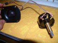
Sorry for being in the dark, but I can't read schematics so I have to surmise. Here's a pic of my starting off point, and I'm thinking I'm wrong already. My neg from the tweeter goes straight back to the neg post - out, correct? (top left of pic) My pos from the tweeter has to go to the l-pad. By following the diag, I'm sending that to pins 1 and 3 (Then the middle goes to the 2 2.7 filters.) Wrong?
Regards and thanks,
Giacomo
Attachments
Hi Giacomo,
I thought the L-pad came with full instructions ?
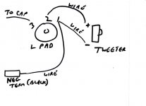
Anyway call the L-pad connections 1, 2 & 3. (2 is the wiper)
The L-pad replaces the tweeter in the diagram, i.e. the
diagram below extends the previous diagram I posted.
T+ is connected to 3.
T- is connected to 1.
The tweeter T- is connected to pin 1 i.e. earth.
The tweeter T+ is connected to 2.
If 1 & 3 are the wrong way round the control will work in reverse.
Note always use a series capacitor when connecting up the tweeter.
sreten.
I thought the L-pad came with full instructions ?
Anyway call the L-pad connections 1, 2 & 3. (2 is the wiper)
The L-pad replaces the tweeter in the diagram, i.e. the
diagram below extends the previous diagram I posted.
T+ is connected to 3.
T- is connected to 1.
The tweeter T- is connected to pin 1 i.e. earth.
The tweeter T+ is connected to 2.
If 1 & 3 are the wrong way round the control will work in reverse.
Note always use a series capacitor when connecting up the tweeter.
sreten.Attachments
giacomo said:Sreten,
Forgetting about the capacitors for now, do you mean like this?
yep, that's right
dave
Not to worry...
Forget the term "ground".
After you connect the capacitor from the amp's + positive output, the + goes to the L pad, then to the tweeter after going through the wiper (variable resistor).
The negative side goes from - on the tweeter to the L pad, then back to the amp.
You do not actually "ground" this type of circuit as you might on a car's DC wiring to the frame. Negative or - serves this purpose.
Think of the circuit as a continuous loop.
Tim
Great, so far I'm on track. Now working back to the first pair of capacitors:
1. I presume they both get wired to the postive on the the Lpad (prong #3)
2. 1 goes to the ON position of the first switch (prong 1) , the other goes to the "OFF" position (prong 3)
3. I don't understand where prong 2 gets wired to at this point. (see sreten's schematic on page 10 of this thread) To which prong of the next switch?
4. Am I correct so far?
5. I also have an air inductor coil that I don't know where to put in the chain.
6. How do I know which switch activates which bandpass/filter?
Thanks for steering me along,
Giacomo
Attachments
Wiring
G
Your drawing is correct but with the question mark lead being a connection wire back to the positive leg of the other portion of the circuit. You could join the end of the lower capacitor and the bottom of the switch together along with your ? wire to form a Y.
The drawing shows one positive leg going across the top of the resistor and the coil where both are connected, then dropping done through the switch to your ?, or Y , now.
Same thing on the bottom with another positive wire running to join the bottom of the resistor and the coil together then up to the junction of ?, where it is joined by a wire out of the bottom of the switch.
If you have a piece of cardboard or thin plywood, lay all this out and hot glue the stuff down, or drill holes and tie it down. The coil is the hardest to anchor, and you'll need a plastic tie wrap or something to hold it in place.
With all 3 switches open you will have the bottom capacitor only in the circuit. The other capacitor is switched in on top and you have the combined value of 5.4 uf (2 x 2.7 uf), which rolls the tweeter off sooner (lower freq).
The two positives at the begiining may be joined, and a single wire then extends to them as output from the amp (another Y).
Tim
Here is the schematic again.
As I said before each switch uses the centre pin and one outside pin only,
which outside pin you use determines which switch position is on or off.
So each "SW" in the diagram is a different switch.
The filter switch should be normally closed - i.e. OFF is closed circuit.
The tweeter switch should be normally open - i.e. OFF is open circuit.
The frequency selector - for high being normal OFF is open circuit.
If your wiring it up to try it - the 5.1R||2.7mH||SWfilter goes in
series with the speaker lead, the tweeter section is wired in
parallel across the speaker leads after the filter section.
You can easily just wire up the tweeter section only and try it.
And then wire up the filter section and try it.
Once you have it working we can discuss the capacitor options.
sreten.
As I said before each switch uses the centre pin and one outside pin only,
which outside pin you use determines which switch position is on or off.
So each "SW" in the diagram is a different switch.
The filter switch should be normally closed - i.e. OFF is closed circuit.
The tweeter switch should be normally open - i.e. OFF is open circuit.
The frequency selector - for high being normal OFF is open circuit.
If your wiring it up to try it - the 5.1R||2.7mH||SWfilter goes in
series with the speaker lead, the tweeter section is wired in
parallel across the speaker leads after the filter section.
You can easily just wire up the tweeter section only and try it.
And then wire up the filter section and try it.
Once you have it working we can discuss the capacitor options.
sreten.Attachments
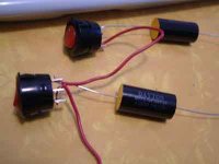
Okay guys, forgive me for having to ask so many stupid questions here, but I'm just not following the concepts too well. Thanks for bearing with me. Following are some pics to clarify.
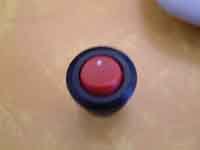
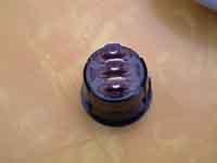
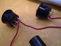
This one is of the front of the switch. The white dot on top will be the on position. If you look at the next pic you will see the prongs. They are vertical and for sake of argument we'll call the top 1 (On) the middle 2 (Neutral) the bottom 3 (off).
You can see from the third pic that the top 2.7 cap is wired to the ON position (prong 1) on the top switch. From the 2 prong I have a wire that goes to the 1 prong (on) on the second switch. From what I gather from the schematic, I am supposed to wire the bottom 2.7 cap to very same 1 prong on switch 2 as well. The red wire from the second switch (prong 2) will then go to the next part of the circuit which we'll deal with later.
Questions:
1. Do I have the caps going to the right prongs or should they both be going to the 'OFF' prong?
2. For my knowledge. What does this accomplish? i.e. what does turning off the first switch (top) do? What does turning second switch do? I'm going to presume the caps are acting as freq filters but since they're both 2.7 and going to the same positive on the lpad I'm not understanding what will be achieved.
3. I'm not sure which is 'filter' switch, 'tweeter' switch, 'frequency' switch. Please label.
Again, sincere apologies for being in the dark and again thanks for all your help.
Regards,
Giacomo
Attachments
One switch controls the filter ON/OFF by bypassing it
- shorting it out. This is the top switch.
One switch turns the tweeter ON/OFF, this is the middle switch.
One switch changes the tweeter c/o frequency this is the right switch.
Normally the switch "dot" is on the bottom and IN is ON - like a light switch.
Normally when the "dot" is IN pin 2 is connected to the the pin on the other side.
Normally when the "dot" is OUT pin2 is connected to the pin on the same side as the "dot".
I really can't see why this is so difficult to understand,
once you understand what each switch is doing.
sreten.
- shorting it out. This is the top switch.
One switch turns the tweeter ON/OFF, this is the middle switch.
One switch changes the tweeter c/o frequency this is the right switch.
Normally the switch "dot" is on the bottom and IN is ON - like a light switch.
Normally when the "dot" is IN pin 2 is connected to the the pin on the other side.
Normally when the "dot" is OUT pin2 is connected to the pin on the same side as the "dot".
I really can't see why this is so difficult to understand,
once you understand what each switch is doing.
sreten.- Status
- This old topic is closed. If you want to reopen this topic, contact a moderator using the "Report Post" button.
- Home
- Loudspeakers
- Multi-Way
- Replacing vintage stereo speakers