Hi, this is my very first post/thread that I've ever created on any forum so please bare with me and I apologize in advance for any newbie mistakes I make.
 Hopefully, I will describe my problem clearly and with enough detail that solutions to this problem will be easily given.
I hope that the pictures I've included will be sufficient enough for a good diagnosis. I desperately need help and I will do my very best to work through this amp repair without wasting too much time of any member willing to help!
OK, so I purchased a Memphis car audio Amp, ST-1000D, approx. 5 years ago and stored it away in my closet as a backup amp during my car audio competition days. Recently, I installed this amp into my Camaro SS show car to push 2 X 12" Memphis Audio sub woofers. Well, after a month of awesome performance, the dreaded red protect light came on and left me puzzled, ITS TECHNICALLY A NEW AMP!
After emailing one of the members on this forum, who was VERY helpful, I got up the nerve to at least open this amp up for a peek. What I found was 4 blown output transistors, 4X IRF3205, and after speaking again with this forum member, I took his advice and replaced all 8 transistors. I ordered 8 new ones but I only replaced the first 4 at first, these were the only ones that had visible damage, but when I re-connected the amp it did not work and the red protect light was back on!
I have now installed the last 4 transistors in that series of 8 and before I go to the trouble of installing the amp again only to see the shiny red light, not to mention that it could destroy all the work I have just done. I did some reading on this forum and found that its better to check some things with a volt meter prior to actually connecting it to a power source.
The problem is, I have VERY limited knowledge about amp repair and using a volt meter for anything other than checking whether or not a vehicle wire is getting 12Volts of constant or switched power from the car battery is absolute greek to me! I may have limited knowledge about amp repair and small electrical parts/components but I am a good solderer and back in my prime, I use to install car audio professionally for 4 years.
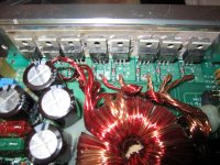
This issue was originally caused by a strand of copper speaker wire somehow getting inside the amp casing and causing this blow out or burning of resistors. You could clearly see where these strands were laying and how they accidentally caused a connection or bridge between one of the output transistors and one of the other electrical parts in front or around it. I need simple terminology and easy to understand information for the average person when any advice is given.
Please have some patience with me because this is my only hope of restoring the BOOM BOOM back into my trunk! The wife has already told me that unless I can fix it myself, without blowing up or burning down the house
, that this would be the "opportunity" for me to downsize my car audio collection!
I did attempt to take a reading from the newly installed IRF3205 transistors by placing the black or (negative) probe to one of the gold blocks that houses the speaker wires when they are installed and I placed the red or (positive) probe on the 1st leg of each of the 8 new transistors. I used the 200K setting on my volt meter and the first four transistors read 22.4K and the last 4 transistors read 69.2K. The resistors directly in front of the newly installed IRF3205 transistors read 22.4K and 69.2K respectively. Is this normal for the first four transistors in the series to have a different value then the last four? Did I damage the first 4 when I attempted to test it the first time, without replacing the last 4 because I saw no physical damage?
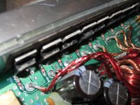
I have included pictures of the amp in question, the 8 new transistors that I installed, and the volt meter that I'm using for the job. I will also mention that the resistor in slot R44 on a schematic, appears to be slightly blackened. It can be seen in the second picture but I'm not sure what size resistor it is or if there is even a problem with it?
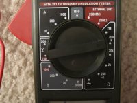
Please be specific about which of the three terminals on the meter that the red and black probes should be plugged into and where the switch/indicator should be switched to or facing when the value of a specific component needs to be checked. As I said before, I need clear direction given along with the advice that any member may graciously offer. Hopefully, this will eliminate me wasting people's time by replying to a post with "where exactly do I put the red probe?"
I know it sounds like I'm an idiot that shouldn't even be fixing this amp but I'm pretty good at fixing most things, including cars, computers, and even engine rebuilding. I have limited knowledge about this subject but I WOULD GREATLY APPRECIATE THE HELP! Thanks in advance to whoever takes the time to patiently read and respond to my novel!
I hope that the pictures I've included will be sufficient enough for a good diagnosis. I desperately need help and I will do my very best to work through this amp repair without wasting too much time of any member willing to help!
OK, so I purchased a Memphis car audio Amp, ST-1000D, approx. 5 years ago and stored it away in my closet as a backup amp during my car audio competition days. Recently, I installed this amp into my Camaro SS show car to push 2 X 12" Memphis Audio sub woofers. Well, after a month of awesome performance, the dreaded red protect light came on and left me puzzled, ITS TECHNICALLY A NEW AMP!
After emailing one of the members on this forum, who was VERY helpful, I got up the nerve to at least open this amp up for a peek. What I found was 4 blown output transistors, 4X IRF3205, and after speaking again with this forum member, I took his advice and replaced all 8 transistors. I ordered 8 new ones but I only replaced the first 4 at first, these were the only ones that had visible damage, but when I re-connected the amp it did not work and the red protect light was back on!
I have now installed the last 4 transistors in that series of 8 and before I go to the trouble of installing the amp again only to see the shiny red light, not to mention that it could destroy all the work I have just done. I did some reading on this forum and found that its better to check some things with a volt meter prior to actually connecting it to a power source.
The problem is, I have VERY limited knowledge about amp repair and using a volt meter for anything other than checking whether or not a vehicle wire is getting 12Volts of constant or switched power from the car battery is absolute greek to me! I may have limited knowledge about amp repair and small electrical parts/components but I am a good solderer and back in my prime, I use to install car audio professionally for 4 years.
This issue was originally caused by a strand of copper speaker wire somehow getting inside the amp casing and causing this blow out or burning of resistors. You could clearly see where these strands were laying and how they accidentally caused a connection or bridge between one of the output transistors and one of the other electrical parts in front or around it. I need simple terminology and easy to understand information for the average person when any advice is given.
Please have some patience with me because this is my only hope of restoring the BOOM BOOM back into my trunk
! The wife has already told me that unless I can fix it myself, without blowing up or burning down the house
! I did attempt to take a reading from the newly installed IRF3205 transistors by placing the black or (negative) probe to one of the gold blocks that houses the speaker wires when they are installed and I placed the red or (positive) probe on the 1st leg of each of the 8 new transistors. I used the 200K setting on my volt meter and the first four transistors read 22.4K and the last 4 transistors read 69.2K. The resistors directly in front of the newly installed IRF3205 transistors read 22.4K and 69.2K respectively. Is this normal for the first four transistors in the series to have a different value then the last four? Did I damage the first 4 when I attempted to test it the first time, without replacing the last 4 because I saw no physical damage?
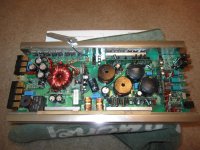
I have included pictures of the amp in question, the 8 new transistors that I installed, and the volt meter that I'm using for the job. I will also mention that the resistor in slot R44 on a schematic, appears to be slightly blackened. It can be seen in the second picture but I'm not sure what size resistor it is or if there is even a problem with it?
Please be specific about which of the three terminals on the meter that the red and black probes should be plugged into and where the switch/indicator should be switched to or facing when the value of a specific component needs to be checked. As I said before, I need clear direction given along with the advice that any member may graciously offer. Hopefully, this will eliminate me wasting people's time by replying to a post with "where exactly do I put the red probe?"
I know it sounds like I'm an idiot that shouldn't even be fixing this amp but I'm pretty good at fixing most things, including cars, computers, and even engine rebuilding. I have limited knowledge about this subject but I WOULD GREATLY APPRECIATE THE HELP! Thanks in advance to whoever takes the time to patiently read and respond to my novel!
Attachments
Last edited:
Hi And welcome to the forum.
1st tip would be to put some line breaks in your post It is very difficult to read when it is one continuous block of text!
You should be able to go back and edit and add some line breaks at appropriate points. Many people will see your post and not bother to continue reading as is.
Tony.
1st tip would be to put some line breaks in your post
It is very difficult to read when it is one continuous block of text! You should be able to go back and edit and add some line breaks at appropriate points. Many people will see your post and not bother to continue reading as is.
Tony.
Ok, I appreciate the advice! I knew my thread looked much different then everyone elses! I will definitely take care of that issue right away! To anyone who may read this and is interested in what I have tried and have not tried, I just hooked the amp up with a 15watt in-line fuse on the B+ wire and it popped it immediately! So there is something wrong!
I will definitely take care of that issue right away! To anyone who may read this and is interested in what I have tried and have not tried, I just hooked the amp up with a 15watt in-line fuse on the B+ wire and it popped it immediately! So there is something wrong!It looks like it is a class D amp with those 2 large coils by the large black Capacitors
the IRF3205 transistors are driving the power supply.
The amp itself may have shorted outputs causing the power supply to go into protect mode
Usually if the power supply is bad, the use will blow immediately after power is applied to the mains. if the fuse is good but protect goes on when remote turn on is powered the amp outputs are likely bad.
Test for shorted mosfets on the left and right channels
I appreciate the advice and I believe you are correct! My knowledge about repairing amplifiers is very limited, as I mentioned the beginning of the thread, so I am not sure how to test the transistors? I described in detail what I did to test them but I am not even sure what I did was correct I the data I got from doing my test means absolutely nothing to me because I have no clue what I am looking for? Please be more specific in how I go about testing these newly installed IRF3205 transistors please! Thanks for your time, it's greatly appreciated!
I realize that I am new but can someone please help me out? I made sure I was very detailed with my question but it seems that newbies don't get much help here? I AM DESPERATE to get this amp fixed but I cannot afford to spend 100 bucks on a repair so can someone please tell me how to check the newly installed output transistors? Thanks
Is there anyone on this forum that can take the time to quickly explain to me how to make sure that the IRF3205 output transistors, that I just installed, are working correctly? I posted a pic of the volt meter I am using to help guide me through this process! Thanks
A volt meter may be enough to tell if the FETs are ok, only as long as they are not installed. It does not suffice to verify correct operation within a class D circuit.
This layout with long transformer wires is a MOSFET killer. The energy stored in parasitic inductance during each switching cycle has to be dissipated as heat in the IRF3205 to end the cycle. I don't see any snubbers or means to control avalanche. btw: Ensure that the transformer is properly glued to the PCB and magnet wires can't rub with car vibration or this will be a long term failure mode.
I see a burned gate resistor in one of the pictures. This IRF3205 surely was bad. The resistor has to be replaced and the other ones checked. The driver components connected to these "gate" resistors also need checking.
A faulty IRF3205 will usually show a short from G to S, or from G to D (burned gate resistor), or more rarely from D to S (since internal connection wires will blow almost instantaneously). A good one will give open circuit G-S and G-D with diode test in both directions (but testing that the gate opens and closes the device is also needed).
Apart from checking for shorts, there is no easy way to ensure that this push pull power supply is working reliably without an oscilloscope, there is not a good design to start with. You can use the amount of idle current draw and IRF3205 heating as a first success indicator. Unequal G-S voltages (measured with meter in DC mode, amp operating) can reveal gate drive problems. However, there are a few things that can go wrong only at high power, resulting in the typical failure pattern after newbie repair: "it fails again and again at high power"
Last edited:
Thanks for taking the time to assist me. I am glad you noticed the resistor as well! I thought there might be an issue with it but again, I have limited knowledge on repairing amps so I was unsure on how to actually test thesistors and I didn't want to go by discoloration alone! This amp was brand new out of the original factory box when I installed it a little over a month ago so any issues with damage that may be caused from wear and tear shouldn't even be a factor! Had it not been for the random strands of speaker wire, I would not be in this situation! The problem I am facing now is that once I connect power, ground, remote wires and a 15amp in line fuse, to prevent frying these 3205's again, the inline fuse pops immediately so I have no way of testing anything with the power on! What is the issue that's causing me not to be able to power it up at this point? Should I replace all the resistors in front of the transistors on the power side? I have already replaced all 8 transistors but obviously there is something that I missed? Anymore advice would be greatly appreciated. Thanks for the advice that's already been given, some of it was a little over my head unfortunately
Does the fuse pop when remote is activated, or even with open remote?
I recommend you to get or borrow a current limited 12V supply, something that can do 10-25A and then fold back to avoid damage. After repair, doing the first test directly in the car is not a good idea, doing it in a work bench is much better.
I recommend you to get or borrow a current limited 12V supply, something that can do 10-25A and then fold back to avoid damage. After repair, doing the first test directly in the car is not a good idea, doing it in a work bench is much better.
Last edited:
You need to check all transistors for shorts in the amplifier.
Output transistors failing will often take out the power supply transistors too if the fuse doesn't blow quick enough or the protect is too slow.
Just to complicate things I have seen blown output transistors taking the class d IC with them.
Output transistors failing will often take out the power supply transistors too if the fuse doesn't blow quick enough or the protect is too slow.
Just to complicate things I have seen blown output transistors taking the class d IC with them.
Is there anyone willing to take the time to actually fix this amp for me PLEASE! I made an agreement with the wife that I would only reinstall this amp back into my car if I could fix it myself! That means I have a VERY limited budget but I know that there is only a bad resistor or transistor that's causing the red protect light to come on! I just don't have the knowledge or time to learn properly to get this amp working again and re-installed by the end of car show season! Please send me offers through a message. thanks
Ok, so what are the parts labeled KO304 and KO307, voltage regulators? I was wondering what the possibility of these being burnt when the power FETS when out?
Also, if the through holes for the transistors lost their solder eye-lits when I was desoldering the old ones, can I solder the legs to the nearest solder point in that same area? For example, the first leg of the power FET connects to the gate resistor so can I solder a joint from the first leg directly to its cooresponding resistor?
Also, if the through holes for the transistors lost their solder eye-lits when I was desoldering the old ones, can I solder the legs to the nearest solder point in that same area? For example, the first leg of the power FET connects to the gate resistor so can I solder a joint from the first leg directly to its cooresponding resistor?
- Status
- This old topic is closed. If you want to reopen this topic, contact a moderator using the "Report Post" button.
- Home
- Amplifiers
- Class D
- Replacing My Memphis Audio ST-1000D blown output transistors. HELP!!!