zigzagflux said:But if we have, in a DC coupled SE gainstage to LTP, at least a hundred volts available at the tail, would the DN2540 cascode not be a great choice in the cathode?
Yes, it is. You've got the voltage you need and the capacitance becomes constant.
SY said:A DN2540 is a particularly felicitous choice for a MOSFET here because that reverse capacitance is only a pF or two. That will probably be swamped by strays.
It's possible (with careful layout) to get the strays down to less than a pF - that's why I like fragile RF bipolar devices when they can withstand the circuit.
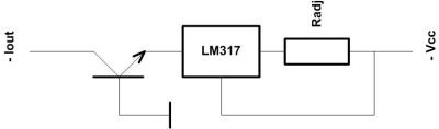
The LM317 make adequate cathode CCS's - much will depend on the bypassing.
In my latest amp I am having real problems getting a robust enough CCS for the cathode's of my output stage. The driver is direct coupled off of a differential pair which is hung off of a -300V negitive rail. The negative rail is solid state and comes up straight away. The PP output stage has +350V B+ (at 50mA per valve) which is valve rectified and comes up with a time delay.
I have built a MJ340 based cascode CCS but it keeps going pop at the slightest provocation. I need something very rugged to withstand the large voltage on switch on, and the considerable initial current rush.
Can anyone suggest good transistor combination for this demanding role and any other design consierations I should be thinking about.
Shoog
oshifis said:SY,
I believed that there is no AC current flowing and there is no AC voltage on the emitter, so the LM317 should not handle any AC.
Sure there is (the collector alone is an ok-not-great CCS), that's why you cascode in the first place. With real devices, hfe isn't infinite nor is hoe zero.
Gary - funny you should say that as its my version of your Tabor.
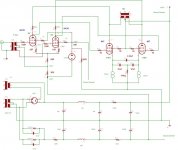
Please find attached the schematic. Its quite remarkable - at the moment I have the amp in the main system. At least one of the CCS is down but it still plays and sounds very nice at low levels. The really amazing thing is that despite the minimal power supply f9iltering and the gross mismatch in current draw on one side - it still has barely any hum at the outputs. The partial feedback seems to be working miracles.
The 807 will try to conduct hard as it comes up. This will ask the CCS to suddenly deal with a high demand for current.
Please find attached the schematic. Its quite remarkable - at the moment I have the amp in the main system. At least one of the CCS is down but it still plays and sounds very nice at low levels. The really amazing thing is that despite the minimal power supply f9iltering and the gross mismatch in current draw on one side - it still has barely any hum at the outputs. The partial feedback seems to be working miracles.
Speaking on inrush current, there is no such thing through a CCS.
The 807 will try to conduct hard as it comes up. This will ask the CCS to suddenly deal with a high demand for current.
Attachments
Shoog,
The output stage CCS has only 18V across it, per your schematic. Anything should work OK there.
Suggestions:
1/ Put a timer in the neg supply rail
2/ use MOSFETs rather than Trs in the CCSs
3/ use a CCS in the input stage as well as the output stage - this is a serious sonic limitation IMO.
4/ I see no provision to balance the output stage currents - across two stages with a LOT of DC gain, even having CCSs in the output may mean all sorts of internal struggles...
5/ The output impedance must be *really* high - do your speakers appreciate that?
Regards, Allen
Shoog,
I tried your circuit (also 807, but with different drive). The CCS in the 807 cathodes were LM317, but it got very hot and finally gave up. Then I ended up with grounded cathode and fixed g1 bias - no problem since then. I did not like the bypassing capacitors, either.
I tried your circuit (also 807, but with different drive). The CCS in the 807 cathodes were LM317, but it got very hot and finally gave up. Then I ended up with grounded cathode and fixed g1 bias - no problem since then. I did not like the bypassing capacitors, either.
My first thought is during startup the 807's are warming up before the 6AU6's. With the local feedback arrangement this will pull the 807's to the B+ rail acting like cathode followers and expose your CCSs' to high voltage. Another possibility is grid cathode arcing during startup which will cause the same problem. Until the 6AU6 starts conducting the grids of the 807's are tied to B+ via the feedback resistors.
The Tabor and 47 both do this- the output CCS is exposed to full B+ during startup. The MOSFETs are well within their ratings during this event.
Look at the SOA (safe operating area) rating of the MJE340. At 50ma the transistor is only good for 150 volts. If you go above this the transistor will likely short. The MJE340 is a delicate part compared to the IRFS820B. Unfortunately at 18 volts you do not have enough headroom to run a self bias CCS. They like a good 40+ volts to perform well.
To run the self bias CCS you could change the input stage biasing slightly to get the 6AU6 plates up to +30 volts or so.
If you have a scope watch the voltage across the CCS's during startup and see what is going on.
5/ The output impedance must be *really* high - do your speakers appreciate that?
Not true at all - the partial feedback arrangement should keep the impedance down to figures comparable to a cathode follower. Difficult to believe but absolutely true. Infact using a pentode in this position actually gives lower output impedance than a triode.
My first thought is during startup the 807's are warming up before the 6AU6's. With the local feedback arrangement this will pull the 807's to the B+ rail acting like cathode followers and expose your CCSs' to high voltage. Another possibility is grid cathode arcing during startup which will cause the same problem. Until the 6AU6 starts conducting the grids of the 807's are tied to B+ via the feedback resistors.
Your analysis seems right on the button. I have a time delay on the +B rail, but still the instantanious start up conditions are likely the same as you describe. I have had a few arc over situations as well - fortunately not tube kill though.
3/ use a CCS in the input stage as well as the output stage - this is a serious sonic limitation IMO.
I may try this. The only thing I was concerned about was whether it would play merry hell with the g2 bias of the 6AU6 (ie if the cathode voltage would jump around) this is why i opted for the resistor. Also its another variable in an already complex mix which introduces another circuit uncertainty.
So everyone is telling me to go for Mosfets - but which ones, and where can I get them. Farnell, my local supplier have a very poor range of self biasing Mosfets - ie none at all.
Shoog
Hi Shoog
DN2540 or 10M45S (or the 10M90S, but this one is pricier and somehow overkill with it 900V rating) seem to be the way to go. Mouser and digikey carry them, but I don't know which one which exactly...neither do I know the prices.
I have some 10M45S, but I would like to have some more (or the DN2540). If you are buying them maybe we can make some european group buy to save on shipping costs.
Erik
Shoog said:
The 807 will try to conduct hard as it comes up. This will ask the CCS to suddenly deal with a high demand for current.
Impossible.
CCS by definition can't give more current than it is set to if it is functional. The harder your 807'th "try to conduct" the less voltage drop you will see on it, but the current will stay still the same.
Watch for voltage peaks that may zener collector-baze junction (see specs in datasheet).
Speaking of currents, a base current may kill the transistor when it's collector does not have a current flow (i.e. when tubes are cold) -- you may look in datasheet if possible base current is in max spec ranges.
For reducing the output capacitance of a CCS, there is the method referred to as the Hawksford cascode, which was used successfully by Gary Pimm in his later CCS designs. This scheme biases the gate/base of the top (output trans.) up from the source (or emitter) degeneration resistor at the bottom device's source (or emitter).
Any gate (or base) capacitive current (from the CCS output terminal thru to the gate/base) then alters the current flow thru the bottom device's degeneration resistor so as to subtract the same current out of the main CCS programmed current. Keeping the total CCS current constant.
Practically, this would require a voltage dropping device like a zener or a string of LEDs between the top gate/base and the degen. resistor. Then a simple CCS is needed to pull up the whole bias string at the top gate/base. (Gary used an LND150 for the biasing CCS)
Don
smoking-amp said:For reducing the output capacitance of a CCS, there is the method referred to as the Hawksford cascode, which was used successfully by Gary Pimm in his later CCS designs. This scheme biases the gate/base of the top (output trans.) up from the source (or emitter) degeneration resistor at the bottom device's source (or emitter).
Any gate (or base) capacitive current (from the CCS output terminal thru to the gate/base) then alters the current flow thru the bottom device's degeneration resistor so as to subtract the same current out of the main CCS programmed current. Keeping the total CCS current constant.
Practically, this would require a voltage dropping device like a zener or a string of LEDs between the top gate/base and the degen. resistor. Then a simple CCS is needed to pull up the whole bias string at the top gate/base. (Gary used an LND150 for the biasing CCS)
Also, practically such compensation can lead to instability on high frequencies.
I have some 10M45S, but I would like to have some more (or the DN2540). If you are buying them maybe we can make some european group buy to save on shipping costs.
That would seem to be the way to go - though I saw in a thread that the 10M45S have been on back order for some very long time. I'm not keen on arranging a group buy after my last one went a little sour.
I'm thinking of sticking to the ring of two type CCS but beefing up the transistor to a TIP50 and placing a 100R resistor on the anode to buffer it a little.
Shoog
burnedfingers said:Better yet I will forget this damn idea all together. Maybe its time for me to pull out and not post here again.
You might try holding your breath until you turn blue, first. I hear that can work.
Really, it isn't clear what you want. I offered you about 6 places to get CCS boards, one of those places being from me, and you got mad. Indeed, Bottlehead offers the exact boards you want, but you just want board, not kits, so you refuse. And really, they are charging for the boards and instructions (from which you might actually learn something -- they aren't bad), not for the $1.00 worth of parts, so you can just throw those out if you feel they are bad for some reason. Also, it turns out that if you send them a nice email, they'll sell you just the boards for a (very) slight savings.
SY offered some of his to you in another thread, but you aparently didn't take him up on them as you are still asking. Geek offered you his, and they weren't good enough (a dremel will make the PCB smaller).
I am sorry I tried to offer help there, and I am kind of already I am offering it here as I assume you are going to tell me I am a bad person for some reason. But, as I see it, your options are to buy what's available, run a group buy yourself, design your own, or take your toys and go home in a huff. Or, maybe you can wait another 2 years and someone else will have some.
- Status
- This old topic is closed. If you want to reopen this topic, contact a moderator using the "Report Post" button.
- Home
- Amplifiers
- Tubes / Valves
- Replacing a cathode resistor with a CCS