Hi 1108,
You might also want to read through this thread when you have some time: http://www.diyaudio.com/forums/tubes-valves/120307-very-low-output-knight-kn928-amp.html
The 928 partial schematics there look remarkably similar to your 728 - same output circuit of quad 6BQ5 tubes @370V (plate) sharing a single cathode bias resistor, same 6CA5 rectifier tube in the power supply. There is quite a lot of good information that Ty supplied in that thread that might apply to your amplifier, too.
The concern about the rectifier tube was mentioned several times, but in the end the unit was repaired and gotten running with no mods to the power supply.
Several times, though, it was mentioned that the stock transformer/power supply was driving the 6BQ5 (EL84) output tubes hard at 370V plate voltage and also running the 6CA4 rectifier at its limit.
Since you are in the market for a new transformer anyway, perhaps going with the lower voltage Edcor would be a consideration. Then, once the amplifier is running, going through the amplifier as you feel the urge, and put in the other modifications suggested here and there.
Whatever you decide to do, looks like a fun little project there!
~ Sam
Hey Eli,
I'm not sure I understand this completely. I'll do a sketch and if you can tell me if I'm on the right track.
thanks
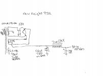
I've prepared some "hen scratches" that show how the B+ PSU should be rebuilt.
BTW, the 6.3 VAC winding of the XPWR178-120 has more than enough "sock" to provide for DC on the phono section heaters.
Attachments
This is great, thanks Eli. I actually had it right. But I do have one more question. After the 100uf cap, do I continue with the rest of the power supply as it is? Meaning this will connect to R64 and everything else will stay the same?
R65 and everything to its right stay. R64 and C1A are replaced by the CLC filter shown on the crude drawing I provided. The new 100 μF. part is the "380" V. source. As you work, if that number is a bit on the low side, it's good. The amp's designer beat the living guano out of everything.
Make certain to replace ALL electrolytic capacitors. Waxed paper caps. are candidates for replacement too.
Talk to McShane about tubes, caps., and an Octal socket. His prices are fair and he doesn't screw you on shipping. Good advice is forthcoming too.
Mouser stock # 553-C14X is the filter choke you need. As piecemeal shipping charges can "eat you alive", now (IMO) is a good time to order a new source selector switch too. Depending on the knob you use, either Mouser stock # 105-14572 (round shaft) or 10WA125 ("D" shaft) is appropriate.
Good advice is forthcoming too.Mouser stock # 553-C14X is the filter choke you need. As piecemeal shipping charges can "eat you alive", now (IMO) is a good time to order a new source selector switch too. Depending on the knob you use, either Mouser stock # 105-14572 (round shaft) or 10WA125 ("D" shaft) is appropriate.
Talk to McShane about tubes, caps., and an Octal socket. His prices are fair and he doesn't screw you on shipping.
Mouser stock # 553-C14X is the filter choke you need. As piecemeal shipping charges can "eat you alive", now (IMO) is a good time to order a new source selector switch too. Depending on the knob you use, either Mouser stock # 105-14572 (round shaft) or 10WA125 ("D" shaft) is appropriate.
Placed my order with Jim. Thanks again for your help
- Status
- This old topic is closed. If you want to reopen this topic, contact a moderator using the "Report Post" button.
- Home
- Amplifiers
- Tubes / Valves
- Replacement PT question