Maybe you guys like a "soft" and "boring" sound? Nothing wrong with that but it's not for me. Here are some quotes i found on the internet regarding Panasonic caps lol;
Well, let me add an extra quote to the list:
After many listening tests in DAC’s and amplifiers, as power supply reservoir cap and as bypass cap, Panasonic FM and especially FR sound more tight and dynamic than Nichicon KZ, UKZ and UKA. I found the soundstage to be more open, with a more controlled and punchy bass, open mids and detailed airy treble.
I must agree Panasonic FC sounds dull. However a harsh or to bright sounding system may benefit from that. So it all depends on the properties of your system.
What role does the zener play in the circuit i.e. what part of the circuit does it feed?
What is the likely dynamic resistance of the zener?
Does the circuit assume or rely on the zener voltage rising quickly when power is applied?
It is easy to change a circuit. It is harder to improve it; first you have to understand the circuit even better than the original designer.
What is the likely dynamic resistance of the zener?
Does the circuit assume or rely on the zener voltage rising quickly when power is applied?
It is easy to change a circuit. It is harder to improve it; first you have to understand the circuit even better than the original designer.
What's it for?
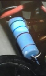
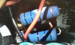
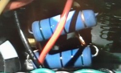
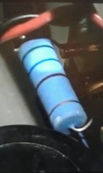
4 watts is an odd size. OEMs order their parts to spec, so if they want 4 watts, someone makes them for them. 5 watts is a standard value, look for that.
And for that matter, if you actually find 4 watt resistors, don't hang up on the 5%. 3%, 2%, 1% work just as well, 560 ohms is 560 ohms.
4 watts is an odd size. OEMs order their parts to spec, so if they want 4 watts, someone makes them for them. 5 watts is a standard value, look for that.
And for that matter, if you actually find 4 watt resistors, don't hang up on the 5%. 3%, 2%, 1% work just as well, 560 ohms is 560 ohms.
What role does the Zener play in the circuit? To be honest i don't understand it myself but i think the following two paragraphs (independent of each other) will give you an idea. It's regarding a Quad 909 by the way.
"The TLC opamp is a DC servo IIRC, not too critical as a result (unlike in the 405) but can be swapped out for something better. The 2134 will work well, since this is the input VAS a good opamp here can make all the difference. Pay attention to decoupling the opamp supplies though - these are zenered down from the main amp rails".
AND ANOTHER QUOTE FROM SOMEONE ELSE
"The TLC271 is not strictly in the signal path per se but acts merely as a DC servo to keep the offset at the output to a low level. Crucially though, this IC adds a signature to the output, not because of intrinsic weaknesses but because it is supplied by the crudest power supply imaginable. Series dropper resistors R3, R4 (3K3) supply 6V8 Zener diodes D1 & D2 respectively from the main voltage rails. There are no decoupling capacitors around the Zeners".
OK. Some versions of the circuit show a 4.7uF decoupling cap on the negative zener. It is a little surprising that even this is missing from other versions. However, I imagine the designer assumed that the integrator capacitor (680nF or 1uF - seems to vary) would get rid of all noise.
Note that DC servos are very much in the signal path, despite the fond imaginings of many people that they are not. Whether zener decoupling is needed or not is unclear to me. A calculation would need to take account of likely zener noise and opamp PSRR, then compare this with thermal noise from the 2.2M DC feedback resistor. The resultant noise is filtered by the integrator cap then attenuated by the 120k and the signal source impedance.
My guess is that something like 10uF across the zeners would do no harm. Whether it would do any good I don't know. I note that the two paragraphs you give contain no calculations, so they probably don't know either.
What role does the Zener play in the circuit? ... - these are zenered down from the main amp rails".
AND ANOTHER QUOTE FROM SOMEONE ELSE
"... it (OPAMP) is supplied by the crudest power supply imaginable. Series dropper resistors R3, R4 (3K3) supply 6V8 Zener diodes D1 & D2 respectively from the main voltage rails. There are no decoupling capacitors around the Zeners".
So originally the OPAMPS have no decoupling at all. Bad engineering! In that case just to decouple to make it text book correct 100nF is more practical than 10uF since the local decoupling is mostly for HF stability. To be effective needs to be as close as possible to the OPAMP's supply pins, which probably is right at the zener pads on the PCB as recommended.
Just do it and be done with it will ya? Then tell us in superlative terms how the amp changed to the better.
So originally the OPAMPS have no decoupling at all.
It's the zeners that are not decoupled
If the opamp is a fairly slow one then it may be happy with no supply pin decoupling. Swapping it for a fast one could create instability problems. Note that for a DC servo you need FET input and low offset; no need for low distortion or very low noise or fast response or high slew rate. The last thing you need there is a 'hot' audio opamp!
I think this is one of those cases where we ought to assume that the designer knew what he was doing. We also ought to assume that the tweakers have not done double-blind tests on their modded amps. We need evidence to adopt a contrary view: evidence of noise or instability with the current circuit, or evidence of actual sound reproduction improvement with the modded circuit.
I think this is one of those cases where we ought to assume that the designer knew what he was doing. We also ought to assume that the tweakers have not done double-blind tests on their modded amps. We need evidence to adopt a contrary view: evidence of noise or instability with the current circuit, or evidence of actual sound reproduction improvement with the modded circuit.
- Home
- Amplifiers
- Solid State
- Replacement Parts for Quad 909


