yes it may well be the wrong thing to use as it is, but ive seen it used in a few of real good amps, mostly highbrid amps or mosfet current amps. and mainly for the outputs or bias feed
as the point of the ccs is to reduce supply hum and variations i
was wondering if it would work, by adjusting the resistor to take into account the voltage drop accross the tranny?
yes diode fed is more popular, twin tranny is arguably a more stable way to do it, especialy if the two trannys are thermaly connected reducing any temp ofsets.
ill look at twin tranny and post back.
cheers, steve
A capacitance multiplier is not the right circuit to use there, a constant current is needed. The current needs to be the same as what was provided by the resistor originally.
The input stage current sets the VAS bias, slew rate and gain-bandwith product of the amp. Too high current will make the amp unstable/oscillate. Too low will give you bad distortion performance and slew rate.
Did you decide to use the 2sk1058/2sj162 fets?
The input stage current sets the VAS bias, slew rate and gain-bandwith product of the amp. Too high current will make the amp unstable/oscillate. Too low will give you bad distortion performance and slew rate.
Did you decide to use the 2sk1058/2sj162 fets?
ok, so on with the show,
ive just been looking at the j500 series current regulator diodes from vishay, has any one seen these? or used these before?
im a touch worried about the tollerance i noticed somewhere on the spec sheet that said 20% but that may be over the total temp range!
http://docs-europe.electrocomponents.com/webdocs/092c/0900766b8092c4f1.pdf
maybe a two lead replacement for the resistor?
im still looking at the twin tranny ccs, but also looking at other things as well, like the j505.
edit, nope my bad, set factory tollerance = + - 20% so at 1ma thats 0.8 to 1.2 ma but at 60pence each, buy 10 and select best?
cheers, steve.
The current regulator diodes were offered as part of an upgrade for the Maplin PCB's by White Noise Audio. On the original PCB its an easy drop in replacement. So might be useful for you existing Amp Boards.
As you say though a bit Expensive/ Noisy/ Wide Tolerance for a new layout. 2 resistors and 2 Transistors don't cost much. they are just harder to retro fit.
")
As you say though a bit Expensive/ Noisy/ Wide Tolerance for a new layout. 2 resistors and 2 Transistors don't cost much. they are just harder to retro fit.
ok so how does this look? finaly got round to doin the twin tranny ccs.
ive put in the var. res. so i can tune for variations in hfe of the trannys.
if im correct in my understanding of the ESP page on current sources
http://sound.westhost.com/ism.htm
then,
I = JV / RE .. and by substitution RE = JV / I
where JV is the junction votage of the tranny/s
and RE is internal res of the tranny, plus the var. res.
0.001 A = 0.65 V / RE there fore RE = 0.65 / 0.001
RE= 650 ohms the nearest value i find from rs. is 649 ohm (pretty close) or a 1k multi turn.
the fixed res should be 10 to 20 times the expected base current,
in the worked example on esp page it works to a 10k res. so im looking at probably a 6k49 res
not sure what to use for the trannys?? was thinking of the same as the input pair? any other recomendations?
cheers, steve.
Attachments
cool, and big cheers to all who have helped on this.
Xoc1,
by bypass i assume you mean ad another cap?
i think you probably mean a small value foil cap? but as the input and feedback caps set high and low pass for the amp, will it not change these points? even if its by a small amount?
what value and type of caps did you use? and did it noticeably change the freq. points?
if they are only small in size i can probly mount them to the bottom of the board, accross the pins of the main caps.
cheers again, steve.
A 0.1uF bipass for the 10uF input and a 0.47uF for the feedback capacitor just help liven up the amp a bit - You should use good quality low esr electrolytics and MKT (or better) bi-pass You could use bigger value caps for the decoupling and feedback to increase the bottom end bandwidth if you want. The original notes say '20hz roll off' for the amp. You could drop this another octave by using a 100uf for the feedback.
The Zobel resistor can be beneficially changed to a non inductive resistor for added stability.
The upper bandwith is set by the 47nf input cap and the 2 off 27pf caps in the second stage.
The Zobel resistor can be beneficially changed to a non inductive resistor for added stability.
The upper bandwith is set by the 47nf input cap and the 2 off 27pf caps in the second stage.
cheers for the info,
the non inductive res for the zobel is a yes. i was looking at these non inductive planar resistors, 64pence for a pack of 5!! cheap as chips.
http://uk.rs-online.com/web/search/searchBrowseAction.html?method=getProduct&R=2391897
either these or something from caddock although they tend to cost a bit.
as for the others, i may put in some extra pads, and do a write up of the optional components to bypass or extend the low end but as i dont use anything under 30hz ill leave the lower point well alone.
47uf and 100uf can be got in the same pin spacing, so ill leave that as is, just add the extra pin holes for a decoupling cap.
so its just the two decoupling caps, and an extra hole for the different spacing of the non iductive res.
ill post up the altered layout when ive done it, cheers again for the help. steve.
they got it wrong last week then, lol..
i went to pick stuff up for work, res and led's packs of 10 and 5 only got charged by the pack, not each.
but as you say, even each, they still a good price.
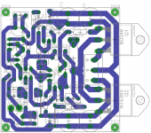
what's the verdict on the board layout as it stands??
just a thought, is it better for the second res of the ccs (the fixed one, R18)
to earth to the main earth (as is) as its part of the power supply? OR, to signal earth, as its part of the input signal circuit??
ill repost the schem and board together so all can share and check my work before i get on to making a pair.
cheers again for the help, steve.
i went to pick stuff up for work, res and led's packs of 10 and 5 only got charged by the pack, not each.
but as you say, even each, they still a good price.
what's the verdict on the board layout as it stands??
just a thought, is it better for the second res of the ccs (the fixed one, R18)
to earth to the main earth (as is) as its part of the power supply? OR, to signal earth, as its part of the input signal circuit??
ill repost the schem and board together so all can share and check my work before i get on to making a pair.
cheers again for the help, steve.
I'd do it like you have it connected now - power supply. If you want you can split the resistor in two and put a cap between the midpoint and positive rail but that might be overkill.
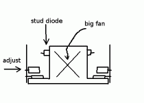
Are you sure you want the output stage bias pot wired like that? You'll have maximum resistance and maximum bias when counterclockwise unless it has a non-standard pinout or bias is adjusted through a hole from the backside of the board.
yes, its through hole. the pot is double sided, top or bottom adj.
although it doesn't show the hole on the board, i forgot that!!
the way im laying out in the box the boards will actualy be upright top side towards the heat sink, so ill adjust from copper side.
see diagram, its a bad drawring but you get the idea.
the stud diodes are twin lead insulated push fit 70amp 600volt and came with the heat sink and there are enough for 8 boards.
cheers, steve.
Attachments
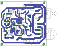
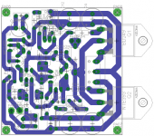
ok, so i put the hole in,
then shifted things around so they fit a little better,
then found a smaller package main power cap. from panasonic that allows me to go up to 330uf and double them up, so its 660uf instead of 220uf as the original was.
hows it looking? i think thats about it?
thanks again to all those who have helped with suggestions and checking my work, steve.
Attachments
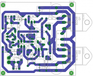
ok so maybe im just tinkering for the sake of it now,
i put in a res to isolate input cap from the base of the input
tranny, splitting the input series resistor either side of the cap.
and an optional cap across the feedback res.
switched the main bias pot to a vert. one, and switched wiring back to clockwise rotation. it may be tight but should have enough room to adjust it.
that is really about it, cant think of anything else, and dont want to over play with the board.
cheers, steve.
Attachments
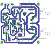
and then i went and updated and uprated the second stage by switching to an mje350 trans. oh well, may as well go the whole way.
input long tail pair and ccs switch to 2sc2240 or mpsa42
q3 and q4 switch to 2sa970
or is that too far? any other mods to think of?
if any one has any comments they will be most welcome.
cheers, steve.
input long tail pair and ccs switch to 2sc2240 or mpsa42
q3 and q4 switch to 2sa970
or is that too far? any other mods to think of?
if any one has any comments they will be most welcome.
cheers, steve.
Attachments
- Status
- This old topic is closed. If you want to reopen this topic, contact a moderator using the "Report Post" button.
- Home
- Amplifiers
- Solid State
- replacement mosfet recomendations??