Hi Mark
I'm using the OpenDRC-DA8. Crossover freq's are 450 and 6300.
Hi Dave, so a 3-way...
How are you allocating the 9600 taps ? I'd probably see how 2048/2048/698 per side works...
G'day MarkHi Dave, so a 3-way...
How are you allocating the 9600 taps ? I'd probably see how 2048/2048/698 per side works...
Yes 3 way horns.
The taps was another one of those area's I'm unsure of.....
So its 2048 when building each filter for bass and mid range then use 698 for the treble. Correct???
Do we build a filter for each driver left and right (total of 6 filters) or just one for each level? At close range the drivers should be very close to identical..
Cheers
Last edited:
Correct, 6 filters. I use the same low, mid, high, filters for both sides.
But that's because all I am trying to do is correct for speaker response and not room response which can vary strongly side to side.
The best way IMO would be to do speaker correction and room correction separately. IOW, do both driver-by-driver for the speaker as we've been talking, and then once that's done, do system level L and R room correction with a separate 2 channel openDRC in the chain in front of the speaker correction. Hope that made sense..
Hi Mark, I think I'm getting the hang of this now.... Thanks
Is there any issue with using lots of eq filters for phase and SPL?
Have been playing with some data to understand using the program and did a couple of trial filters. I used the first bank of eq sliders with a broad Q to get an overall flat phase response then used another bank with sharper filters to complete a nice smooth trace. This uses a lot of filters, too many?
What is our phase target, +/- ?
Not sure about the impulse setting? FTT length? Does changing these settings really make much difference?
Once the filter is created there's a message at the bottom of the Impulse setting section, whats the offset?
I think thats about all the questions for now, until I get back home and can do some real testing...
Once again thanks for your help. Appreciated!
When you measure phase angle from speaker system. How good is the microphone and soundcard??
Do you all guys compensate for the microphone amp and soundcard phase rotation?
The best way would maybe to measure up the phase rotation first and compensate for that in the SW?
Do you all guys compensate for the microphone amp and soundcard phase rotation?
The best way would maybe to measure up the phase rotation first and compensate for that in the SW?
When you measure phase angle from speaker system. How good is the microphone and soundcard??
Do you all guys compensate for the microphone amp and soundcard phase rotation?
The best way would maybe to measure up the phase rotation first and compensate for that in the SW?
When using REW there is possibility to have measurements corrected automatic and info to do that is to find in their help menu, roughly it means you have calibration file for analog chain loaded in "Preferences" then "Soundcard" tab, plus microphone calibration file is loaded in "Preferences" then "Mic/Meter" tab. Can also think of two ways to have calibration manually added later to old saved measurements without actual right calibration set when measured, first is over at left side for each measurement tabs hit "Change Cal...." and there's menus to either point to new or clear old soundcard and microphone calibration files, second way to calibrate could be in manual manner for a new measurement at "All SPL" tab do the math of the new measurement X (times) calibration should do it.
Hi Mark, I think I'm getting the hang of this now.... Thanks
Is there any issue with using lots of eq filters for phase and SPL?
Have been playing with some data to understand using the program and did a couple of trial filters. I used the first bank of eq sliders with a broad Q to get an overall flat phase response then used another bank with sharper filters to complete a nice smooth trace. This uses a lot of filters, too many?
What is our phase target, +/- ?
Not sure about the impulse setting? FTT length? Does changing these settings really make much difference?
Once the filter is created there's a message at the bottom of the Impulse setting section, whats the offset?
I think thats about all the questions for now, until I get back home and can do some real testing...
Once again thanks for your help. Appreciated!
Hi Dave, it does sound like things are coming together for you. You just needed another relative beginner like me to translate the experts more technically accurate advice lol.
I do EQ the same way you describe, broad Q on bank 1, finer Q on bank 2, etc. When Pos added the bypass buttons, this makes it doubly advantageous IMO, to add eq iterations in separate banks.
I'm guessing it makes no difference how many eqs, but that the amount of gain and Q on individual filters matters more.
I would like to know that for sure though, along with is it OK to use different types on EQ on different banks (eg constant Q on one bank, cosine on another)
Phase target? At 1/6 smoothing, I like to be with 5-10 deg. The problem is always at the high and low ends of each passband, particularly if you're short taps for the low end. At very low freqs, you may well be better off living with a smooth increase in phase, rather than trying to force it to flatten.
I don't know much about FFT length...and use whatever comes up with # of taps input.
I think offset is the highest peak above 0dB generated by the file.
Believe it matters if you're using a fixed point processor, but not if floating. But I could be full of crap here...don't even know where i got this idea.
Phase target? At 1/6 smoothing, I like to be with 5-10 deg. The problem is always at the high and low ends of each passband, particularly if you're short taps for the low end. At very low freqs, you may well be better off living with a smooth increase in phase, rather than trying to force it to flatten.
Wesayso found that forcing the phase flat right to the bottom sounded strange to him. Allowing the phase to resemble the natural rolloff of the cabinet at the lower end worked better. Trying to force it flat to DC seems like something that isn't a good idea and can use a lot of resources in a tap limited dsp system.
If you use minimum phase EQ to correct your frequency response it will also tend to correct the phase response as well. A flat frequency response should give a flat phase response. Using minimum phase filters to EQ and linear phase filters for crossover can help or you can try and correct the phase response afterwards.
Byrtt makes some good synthetic curves that show the minimum phase behaviour of various frequency response curves. These can be a good guide as to what to aim for to get a more natural response.
When using REW there is possibility to have measurements corrected automatic and info to do that is to find in their help menu, roughly it means you have calibration file for analog chain loaded in "Preferences" then "Soundcard" tab, plus microphone calibration file is loaded in "Preferences" then "Mic/Meter" tab. Can also think of two ways to have calibration manually added later to old saved measurements without actual right calibration set when measured, first is over at left side for each measurement tabs hit "Change Cal...." and there's menus to either point to new or clear old soundcard and microphone calibration files, second way to calibrate could be in manual manner for a new measurement at "All SPL" tab do the math of the new measurement X (times) calibration should do it.
Hello,
I always enter my microphone calibration file (and the its phase relative data) in REW.
I find sometimes useful to change of calibration file when the source is not in front of the microphone, angled calibration files are requied to be accurate in this case since the microphone response is changing with angle, but i was not aware about the soundcard phase rotation...
How can you measure and correct it please ?
Wesayso found that forcing the phase flat right to the bottom sounded strange to him. Allowing the phase to resemble the natural rolloff of the cabinet at the lower end worked better. Trying to force it flat to DC seems like something that isn't a good idea and can use a lot of resources in a tap limited dsp system.
If you use minimum phase EQ to correct your frequency response it will also tend to correct the phase response as well. A flat frequency response should give a flat phase response. Using minimum phase filters to EQ and linear phase filters for crossover can help or you can try and correct the phase response afterwards.
Byrtt makes some good synthetic curves that show the minimum phase behaviour of various frequency response curves. These can be a good guide as to what to aim for to get a more natural response.
Think good idea reminding us about this thanks fluid.
First after getting modern DSP power also myself went nuts and had flat phase even out at system stop-bands impressed by the better realism but must say after wesayso shared findings that for me he's right in it takes some general relaxing joy from system going from all genres and tracks sound great to be more track dependent and less foot tapping : (
Shall absolute not dictate how individuals calibrate their system that is free choice but can share own findings and recommend at least try out by trials at system stop-bands have phase that follow actual amplitude response, its pretty easy create and load some correction files with the different phase tracking build in and take longer listening sessions after that. Have a track title "Revelation" by Robben Ford where rhythm timing between instruments fall totally apart when phase is flat down to DC potential, can only guess on reason could probably be because musicians under recording monitor their own timing relative to other instruments via monitors that have some normal point of minimum phase roll off.
That said in visuals for audio band don't think there's so much difference between first two below, what rocks seems correct for XO points and to cut that out used by purpose 8th order XO point for 100Hz sub below.
Attachments
For me, the change between flat phase at the listening spot out to DC and following the actual FR drop off was much more easy to detect than a more relaxed phase at the bottom end. The difference was in the sense of rhythm.
As BYRTT mentions this was track dependent. So for myself I'd rather have a more "relaxed" phase bottom end (at the listening position) than true linear phase.
This made me shoot for minimum phase behaviour all trough the pass band (at the listening position).
I don't have crossovers. But I did have a phase error happening at the baffle length of my arrays when measured at the listening position. While I used a different tool I manipulated that phase anomaly to get my minimum phase response at the listening position.

Be aware that frequency dependent windows in REW are smoothed when compared to some other tools like DRC-FIR and APL TDA.
Original link: http://www.diyaudio.com/forums/full-range/242171-making-two-towers-25-driver-full-range-line-array-191.html#post4620292
For your information, my phase manipulation is based on a less than 3 cycles frequency dependent window. But not one as available in REW. Just thought I should mention this.
As BYRTT mentions this was track dependent. So for myself I'd rather have a more "relaxed" phase bottom end (at the listening position) than true linear phase.
This made me shoot for minimum phase behaviour all trough the pass band (at the listening position).
I don't have crossovers. But I did have a phase error happening at the baffle length of my arrays when measured at the listening position. While I used a different tool I manipulated that phase anomaly to get my minimum phase response at the listening position.
Be aware that frequency dependent windows in REW are smoothed when compared to some other tools like DRC-FIR and APL TDA.
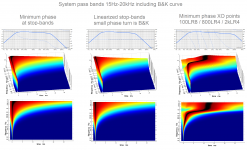
a measurement borrowed from ra7, manipulated by me to show differences between REW and DRC-FIRQuoting myself again... hmmm
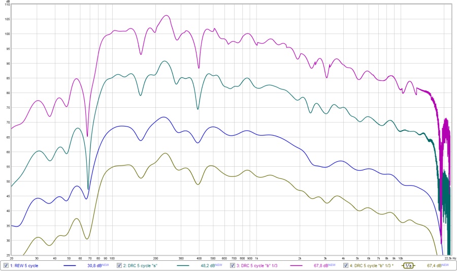
The top graph is DRC doing a 1/3 octave 5 cycle window. (MPPrefilterType = b and MPBandSplit = 3)
Second one is DRC's sliding window (my favourite)
Third graph is REW's 5 cycle window
Fourth graph is DRC's 1/3 octave 5 cycle window we saw, but smoothed 1/6 octave.
In hindsight I see why, knowing the result of the first type of a frequency dependent window that was introduced in REW. Well, this satisfies all of my curiosity.
case closed?")
Original link: http://www.diyaudio.com/forums/full-range/242171-making-two-towers-25-driver-full-range-line-array-191.html#post4620292
For your information, my phase manipulation is based on a less than 3 cycles frequency dependent window. But not one as available in REW. Just thought I should mention this.
Last edited:
Very helpful explanations and illustrations guys ! Nice indeed.
While we are talking about the merits (or lack) of phase linearization at the lower end of the spectrum, it kind of begs the related issue of how many taps are being used..
So may I ask how many taps are folks using?
While we are talking about the merits (or lack) of phase linearization at the lower end of the spectrum, it kind of begs the related issue of how many taps are being used..
So may I ask how many taps are folks using?
... at "All SPL" tab do the math of the new measurement X (times) calibration should do it.
That postulate from post 1707 is stupid wrong
should read:... at "All SPL" tab do the math of the new measurement / (over) calibration should do it.
Very helpful explanations and illustrations guys ! Nice indeed.
While we are talking about the merits (or lack) of phase linearization at the lower end of the spectrum, it kind of begs the related issue of how many taps are being used..
So may I ask how many taps are folks using?
65536 Taps. Why? I guess because I can...
Hello,
I always enter my microphone calibration file (and the its phase relative data) in REW.
I find sometimes useful to change of calibration file when the source is not in front of the microphone, angled calibration files are requied to be accurate in this case since the microphone response is changing with angle, but i was not aware about the soundcard phase rotation...
How can you measure and correct it please ?
REW can correct soundcard or hole device chain automatic if you follow its help file or hints in post 1707, be aware in HF area calibration files is some sample rate dependent.
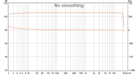
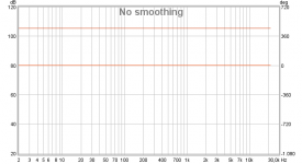
You can measure soundcard performance manual by hardwire loop I/O and run a measurement session in REW, below is a onboard ALC892 audio-codec measured without any other calibration file loaded so what we see is sum of I/O AC filters but we can't know what difference from perfect is coursed by input and what is output without use of another reference point.
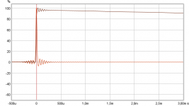
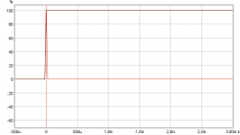
Manual correction can be done with above loop measurement, get its IR centered with "Estimate IR Delay" and save measurement so it can be opened once more and offset the second one so SPL is at zero dB point and save this measurement as correction file for this particular soundcard loop at that used particular samplerate. Proof is on "ALL SPL" tab then "Controls" take the "first measurement" as A / (over) B where B is "correction lowered to zero dB", these two after push "Generate" button sum as perfect IR seen below.
If you adjust REW with soundcard calibration file its then reference flat between I/O so that any audio device placed in loop can be benchmarked be it pre or power amps but be carefull with power amps and use some resistor network at their output, also some power amps that are of bridge type have trouble because negative speaker connector is floating and has no in common with input ground.
Best precision in REW is probably not only loop back soundcard but have microphone preamp and power amp inside loop too and set as calibration file in "Preferences" "Soundcard" tab.
Attachments
Last edited:
Best precision in REW is probably not only loop back soundcard but have microphone preamp and power amp inside loop too and set as calibration file in "Preferences" "Soundcard" tab.
Agreed for sure. Wouldn't the microphone preamp (non USB mic) be included in the soundcard calibration, since the loopback is analog out back into analog in?
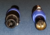
Adding the power amp into the equation is a step I almost never hear about...
I got these adapters in a few weeks ago to make that measurement....
I call them " Danger Will Robinson !! "
Attachments
65536 Taps. Why? I guess because I can...
Why not
OK, I've kind of owed all you guys, especially 1201, an update about me quest for a small form convolution box that can also handle live input...
A linux box is where I'd like to get to, but I can see that is going to be a bit of a learning project before it's up and running...
So in the meantime, I took an easier route and repurposed the jriver ID into a Win7 box with pretty much nothing but jriver MC on it. No auto updates, not online, always on, etc.
I'm pretty happy with it really...it's hot swap-able HDMI head/headless, with remote control by phone/tablet (android).
Handles 8 channels of convolution, external sdif input via miniStreamer and WDM, and outputs via USB to either the UMC1820 or x-32. I can probably get either of those devices to also handle the external input, but I kinda like the only path back into jriver being thru the ministreamer, as I'm quite scared of inadvertently making a feedback loop...
Just got through testing REW with it, and even loopback is working fine.
The FIR files I'm using are the same ones I have in the minidsp boxes, only taps are increased 3X. Phase comes out less straight line with jriver...my guess is parametric phase adjustments that wouldn't fully take with 6k taps available with miniDSP, do take with the 18k I'm using in jriver, ...making phase more wobbly because I overcorrected trying to make 6k work..
So I'm going to do a complete FIR rebuild, probably with 24k taps on all passbands. Hence one of the reasons I'm asking about folks taps utilization.
My guess is 32k is about all the little NUC is good for...
It's going to be interesting to try to A/B the sound between the two setups.
And measuring the power amps too https://www.google.com/search?q=Dan...on&aqs=chrome..69i57&sourceid=chrome&ie=UTF-8
Last edited:
Agreed for sure. Wouldn't the microphone preamp (non USB mic) be included in the soundcard calibration, since the loopback is analog out back into analog in?
Adding the power amp into the equation is a step I almost never hear about...
I got these adapters in a few weeks ago to make that measurement....
I call them " Danger Will Robinson !! "
"Danger Will Robinson"
scary vision for poor little sensitive mic/line input.You right many have soundcards have universal input that in setting can be set as line in or microphone pre amp sensitivity, myself on preferred computer have only normal line in and in that microphone also need phantom power use a little cute Behringer mixer XENYX 802 to interface devices.
Regarding how many taps are folks using? Well that's a secret when JRiver locks ASIO driver up at 192Khz I/O
can say wesayso run small numbers and poor AMD A8-3870 that will be replaced because the other brand have much better single threaded performance and less power demand toggle in 20-30% area.Thanks for your explanations, since i'm on a computer i always set the sample of everything a 48k and I will try to calibrate soon at the output amps just for funREW can correct soundcard or hole device chain automatic if you follow its help file or hints in post 1707, be aware in HF area calibration files is some sample rate dependent
I call them " Danger Will Robinson !! "

It worked perfectly !
My mackie interface is immune to the 48v DC on the ouputs

I'm not sure that the Berhinger are protected against that mistake (others people should be careful)
- Home
- Design & Build
- Software Tools
- rePhase, a loudspeaker phase linearization, EQ and FIR filtering tool