May I suggest this kind of discussion should probably take place on a dedicated thread?
Yes, I will make a dedicated thread.
Is there a tutorial on how to get rephase and REW to work with foobar?
Hello,
In a few words, once you have made the measurement with Rew, then export this measurement to rePhase,
in txt format, create the correction and generate the impulse in .wav 32 bts.
In foobar, you need foo-convolve.dll component
foobar2000: Components Repository - Impulse Response Convolver
place it in the active dsp chain and configure it, selecting the impulse you made with rePhase.
cdt.
Other solution is to use Equalizer Apo which allows convolution ( wav files).
No need to install foobar complements, and will also work with any Win app ( youtube, internet radios, etc...).
https://sourceforge.net/projects/equalizerapo/
Interesting too because allows mix of iir and fir filters.
A bit on the down side, it works on wdm windows drivers, no asio. Though for me not a problem...
Last edited:
First i did measurements with HOLM tried to export it to REW... ((+-&_€#@*"* (sorry for my bad language).
SW is not my bag... Thanks jmbee and GDO. Maybe i offer someone a flight ticket to Sweden gettin it all to play.
I did several measurements on my system in outdoor environment (echo free) no wind and dead quiet ��
Quad esl 63 ( modified..) has +/- 20 deg phase shift depending on mic position also. Pretty straight freq resp. But when i connect my active crossower 24db linkwits @ 150hz to my hommade dipole subwoofers it went messy with the phase. Between 17 hz hz and 150hz i got 5x360 =1800 deg phase shift just from the active crossover. I really hope to get the bass more tight then today. Qts of the dipole bass element is 0.65 so its a quite good start.
Then in my listening room i have a infra subwoofer playing between 15 and 28 hz. I will measure phase and delay later. Frequency response is ok... Its 4x15" 600w each woofers built in the wall, using my garage as box volume. 120 cubic meter or if it is my listening room 100cubic meter that is the box?? Anyway it moves a lot of air and its quite low distortion. Next step will be to use rephase even on ths infra sub as well. When i have learned it.
esl 63,
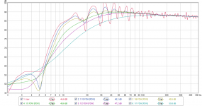
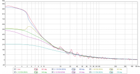
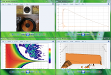
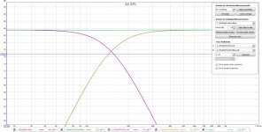
For inside environment measurements below 100Hz there is so much minimum and non minimum phase room response involved that it gives so much "Excess phase" when you in REW ask for "Min phase" curve of your frq response compared to measure absolute phase, so using some windowed settings to filter out room helps a lot. Below curves "Overlays" view is example same measurement inside a room system but one is raw, one is FDW (frq dependent window) width in octaves 1/10, one is FDW 1/6, one is FDW 1/3, one is FDW 1/2, and finally one is FDW 1/1, guess for your very low frq woofers use FDW 1/3 to base correction and from say 100Hz and up base your correction on FDW 1/6. I don't say this is the perfect settings for your room but try experiment and see the differences, its pretty easy when having one measurement to save it and then open it multiple times in same session and then set different window settings for each of them and toggle thru results, and to save that multiple session pick "Save all measurement".
For inside environment measurements below 100Hz there is so much minimum and non minimum phase room response involved that it gives so much "Excess phase" when you in REW ask for "Min phase" curve of your frq response compared to measure absolute phase, so using some windowed settings to filter out room helps a lot. Below curves "Overlays" view is example same measurement inside a room system but one is raw, one is FDW (frq dependent window) width in octaves 1/10, one is FDW 1/6, one is FDW 1/3, one is FDW 1/2, and finally one is FDW 1/1, guess for your very low frq woofers use FDW 1/3 to base correction and from say 100Hz and up base your correction on FDW 1/6. I don't say this is the perfect settings for your room but try experiment and see the differences, its pretty easy when having one measurement to save it and then open it multiple times in same session and then set different window settings for each of them and toggle thru results, and to save that multiple session pick "Save all measurement".
Attachments
Congrats to swedish hockey!
Outdoors measure the sub without filter, then the software can more easily find "sync"
Group delay and phase of the elecronic filter can be found from fig 6:
JAES papers
Or measure the lowpass section of the filter electrically, import and convolve with unfiltered SUB in REW
Or make a LR 24 minimum phase FIR i RePhase, import and convolve with unfiltered SUB in REW
Last edited:
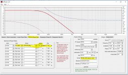
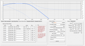
Enclose pictures of LR 24 filter from RePhase in REW.
The excess phase can be confusing if you are used to normal electrical magnitude/phase plots.
The excess phase can be confusing if you are used to normal electrical magnitude/phase plots.
Attachments
Last edited:
...I really hope to get the bass more tight then today...
If you ask me that will happen when you down the road have each pass-band set right and if ctc distance is fair good then linearize the excess phase from minimum phase (IIR) XO point. Generally XO points down at 150Hz and below is not easy in real world rooms so have patience and curiosity doing measurements to learn from, suggest for simplicity start with get ESL 63 to cooperate perfect with dipole bass element and forget about infra subwoofer until the other pass-bands cooperate perfect because it fast gets more complicated align 3 pass-bands than 2 pass-bands and especially at those low frq points in a real world room. As torgeirs showed Rephase is helpful for other than set the real filters in it can output target responses than when imported to REW you have the textbook curve to align up to in a overlay window when tweaking system response. To make textbook target curve for your dipole bass element look below visual example from Rephase, its relative important to set sample rate to same as measurement chain, and when file is imported or dragged into REW get IR (impulse response) zero aligned either manual or use button "Estimate IR Delay". Attach a couple of good documents from out there one about alignment for low frq and one for nearfield low frq measurement.
Have a two-way exercise project myself running XO point down at 180Hz and while it got pretty good data measured up front at about 70cm it taken several days to get there because of room influence at these frq and also because try to realize steep 16th order filter which is not so easy as i thought it was, and soon when its correction is polished a bit more up front then comes the out in room measurements and everything that was nice looking probably fall apart again and needs room correction if possible : )
Attachments
Last edited:
Hockey? is that the thing they do on a slippery isy floor chasing some plastic whatever.. I prefer soldering smoke in the basement flipping the nobs on my notch filter making fft plots... I forgot to say that i also have DIPOLE compensation filter that contribute to the phase shifts. i guess thats why it rotates 5 turns.
@ BYRTT, Fig 3: Guess the measurement of the bass is without LP filter as the SUB can track the risetime of the mids.
@esl 63: Okay, that explains it, but still measurements without filters is good referenses to have when analysing the behaviour in room.
Guess you have already read the Linkwitz site when it comes to integrating dipoles i room.
The REW Room SIM is also excelent for simulating bass responce in room. Gives an idea of what is obtanable.
I also like the Multiple Subwoofers: Optimize Them With Multi-Sub Optimizer Software
Guess the IIR filters can be implemented with RePhase also.
Sorry for the sports comment")
@esl 63: Okay, that explains it, but still measurements without filters is good referenses to have when analysing the behaviour in room.
Guess you have already read the Linkwitz site when it comes to integrating dipoles i room.
The REW Room SIM is also excelent for simulating bass responce in room. Gives an idea of what is obtanable.
I also like the Multiple Subwoofers: Optimize Them With Multi-Sub Optimizer Software
Guess the IIR filters can be implemented with RePhase also.
Sorry for the sports comment
@ BYRTT, Fig 3: Guess the measurement of the bass is without LP filter as the SUB can track the risetime of the mids...
Sorry not sure understand your technical language because woofer is pretty heavy LP filtered (specs below)
can you point me other way to what you specific mean. Can say its a two way exercise speaker and i'm not satisfied and finished calibrate it, have observed four points myself that is not satisfying and need attention, one is step response attack side fly much too high but maybe its coupled and gets better when second point is corrected that system have too much excess phase at very lows compared to amplitude response and third thing is mid-tweeter sits in a foam core enclosure that is ratling and can be seen in impulse response from 750uS-1,2mS plus in wavelet and waterfall, XO point at 180Hz is bit too low number for mid-tweeter 10F/8424 and that also push to foam core ratling. Overall exercise is to hear how flat baffle system sounds when XO point is within 1/8 wavelength as with Synergy concept and at same set XO slopes to 16th order LR because that combined ctc distance within 1/8 wavelength plots out in XDir simulation as perfect vertical power response. XO slopes and drivers general linearizing EQ is all set with IIR filters but XO points excess phase is linearized with FIR filter and fourth point to look at is still have some very small corrections around XO point to do yet, at first was surprised how hard it was to set a right summing 16 order slope but after some hours work with it can see why : ) had it set up for a couple of weeks with 8th order but like this hobby and tumbling with problems as this 16 order gives enroute more correct settings.
Last edited:
Huge thanks to JohnPM, the author of REW, who has kindly added some of the functions necessary to facilitate the room correction process based on multiple measurements in the last Beta version (V5.19 Beta 5) of REW.
Among the new features:
- the possibility to time align a batch of measurements, which is mandatory prior to making arithmetic on these measurements (sum, averages, aso...)
- the possibility to generate the excess phase of a measurement, in order to be able to export this excess phase to rePhase, and generate the appropriate correction to obtain a minimum phase correction impulse.
These are huge developments for the interaction between REW and rePhase in the field of room correction.
Thanks again John
May I suggest you download Convolver-VST and read up on making a config file. Search on 'convolver' and you'll find all of it. This can be put into foobar's DSP stack, can have multichannel output mapping, delays and all sorts of good things. It will host your .wav FIRs from RePhase. You will need the vst plugin for foobar.Is there a tutorial on how to get rephase and REW to work with foobar?
I have been trying for almost a week... there is a good tutorial for jriver i know.
I Use Windows PC, REW, rephase, foobar.
Thanks
That is greats news!Huge thanks to JohnPM, the author of REW, who has kindly added some of the functions necessary to facilitate the room correction process based on multiple measurements in the last Beta version (V5.19 Beta 5) of REW.
Among the new features:
- the possibility to time align a batch of measurements, which is mandatory prior to making arithmetic on these measurements (sum, averages, aso...)
- the possibility to generate the excess phase of a measurement, in order to be able to export this excess phase to rePhase, and generate the appropriate correction to obtain a minimum phase correction impulse.
These are huge developments for the interaction between REW and rePhase in the field of room correction.
Thanks again John
(and not only for room-related corrections
)Sorry not sure understand your technical language because woofer is pretty heavy LP filtered (specs below)
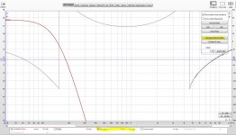
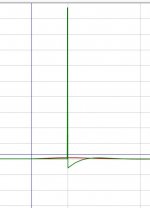
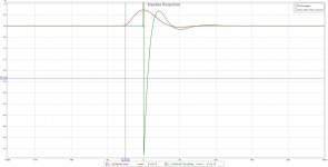
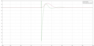
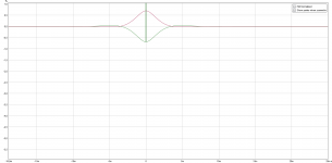
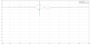
Have enclosed three pictures of Linkwitz reily 150 Hz, minimum phase, 24db/oct filter made with Rephase.
In REW the impulses can be imported can be seen in picure 1 to 3
- Both LP and HP scaled to 100%
- Scaling acording to energy in signal
- Zoomed to see 150Hz LP better
So the LP channel can not track the HP channel when rising from zero.
They are aligned at the top value of each impulse.
The LP filter has a lobe of about 6ms. That is 180Hz, so it is according to theory that shorter wavelengths are removed.
Attachments
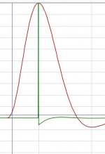
Argh forgot to make "minimum phase version" first.
And of course the a minimum phase filter is causal and LP and HP section time function starts at the same time.
And of course the a minimum phase filter is causal and LP and HP section time function starts at the same time.
Attachments
Hi torgeirs,
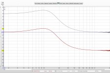
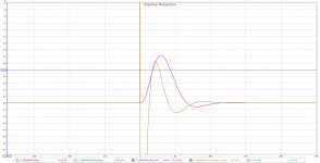
Myself had not before looked at IR in that view mode before so to learn had to replicate your simulation.
From that can i friendly say it looks you had to change assumptions how a summed system IR shall look like, reason is by mistake you take a minimum phase IR for woofer and move it forward to align IR top value with a minimum phase IR for mid-tweeter and that probably don't sum very good as a textbook linear phase XO point, in same scale as your visuals first one below is minimum phase version of 150Hz LR4 that align at attack of IR and second one is the linear phase version that align at IR top value, third one is textbook version how my exercise system including stop bands should look like.
Myself had not before looked at IR in that view mode before so to learn had to replicate your simulation.
From that can i friendly say
it looks you had to change assumptions how a summed system IR shall look like, reason is by mistake you take a minimum phase IR for woofer and move it forward to align IR top value with a minimum phase IR for mid-tweeter and that probably don't sum very good as a textbook linear phase XO point, in same scale as your visuals first one below is minimum phase version of 150Hz LR4 that align at attack of IR and second one is the linear phase version that align at IR top value, third one is textbook version how my exercise system including stop bands should look like.Attachments
- Home
- Design & Build
- Software Tools
- rePhase, a loudspeaker phase linearization, EQ and FIR filtering tool