Yep, it looks like it does. It will work for the small signal units just fine. I'm not sure it will have enough drive to test the big outputs; you'll just have to try and find out.
Also, I didn't know if you knew about Nelson's DIY site. I'm forwarding this for reference because the articles are outstanding.
Also, check out the galleries to see what others have built (including Alephs)...
http://www.passdiy.com/
Also, I didn't know if you knew about Nelson's DIY site. I'm forwarding this for reference because the articles are outstanding.
Also, check out the galleries to see what others have built (including Alephs)...
http://www.passdiy.com/
It's actually pretty simple. (not being condescending at all)
1. Interested in trying Aleph? Yes or No If yes, skip #2
2. Repair 400a? Yes or No If yes, skip all other questions
3. If #1 yes, then which Aleph?
4. If we have 220v primaries, we can reduce the power supply voltages down to build a smaller Aleph 30. You'd wire the xformer for 220v and it would supply voltages that are half of what they are currently. (unless we also have lower voltage secondary taps)
5. If we only have 120 primaries and no lower voltage secondary taps, then we have to build a larger Aleph 2 because the power supply voltages we're stuck with are higher. The higher the power supply voltage, the more devices you need because it runs hotter.
6. Also, we haven't talked about what you are driving for speakers. Do you need the higher power of the Aleph 2 (think big room heater) or is the smaller Aleph sufficient (sweeter sound).
It really comes down to whether or not you want to keep it as a 400a or try something new just for fun. Figure the cost will be the same for both. (Actually, it will be less for the Aleph because you won't be buying TO3 output devices unless you want to)
Well the saga continues.. I was just about to fire up the "good" channel with a variac and noticed the same resistor on that side is also toasted.. So I can only assume both sides are pretty damaged I guess..
I dont know what the sonic qualities are of the DIY designs.. I can only assume he improved things? that being said; I think if I can wind up with a better sounding amplifier than my existing 400a (cranking up some vinyl Rush music at the moment") ) I'd like to try the project?? Am I nuts? I go from trying to repair a piece of art to a project.. will I be banned from this site?
) I'd like to try the project?? Am I nuts? I go from trying to repair a piece of art to a project.. will I be banned from this site?
I am driving some Vandersteen 2ce's in a small to medium sized room.. they are known to be power hungry but I can say this; the 400a has no problem driving these to the point where I am sure if I wanted to the built-in warning LED's would start flashing (its dangerous to even try to get them to flash so I have refrained from such madness)...
The thing is is that I suspect I will have relatively low chances of success of this project unless this forum is able to help me.. so if that is the case I am game..
Based on what I have told you can you help me choose a design?
I dont know what the sonic qualities are of the DIY designs.. I can only assume he improved things? that being said; I think if I can wind up with a better sounding amplifier than my existing 400a (cranking up some vinyl Rush music at the moment
) I'd like to try the project?? Am I nuts? I go from trying to repair a piece of art to a project.. will I be banned from this site? I am driving some Vandersteen 2ce's in a small to medium sized room.. they are known to be power hungry but I can say this; the 400a has no problem driving these to the point where I am sure if I wanted to the built-in warning LED's would start flashing (its dangerous to even try to get them to flash so I have refrained from such madness)...
The thing is is that I suspect I will have relatively low chances of success of this project unless this forum is able to help me.. so if that is the case I am game..
Based on what I have told you can you help me choose a design?
Okay, first things first.
I need you to double check your post regarding the transformer wire codes.
Also, you mentioned that there are wires shrink wrapped under it. We need to know what colors those wires are.
Also, check the terminal strip near where the power comes into the unit. Are there transformer leads there also with nothing hooked up to them?
Lastly, check the back of the unit and see if it mentions 220 volt anywhere on it.
Anyone on the forum know if the 400a transformer also has 220v primaries?
You may have missed this:
EDIT: from the top of the xformer:
WESTERN
CODE 377
WTI NO 2199B
PRI-100v=WHT-Gray
12v=WHT-BLK
SEC-88v6a BLUE-BLUE
646av6a Blue-Black
There is only one wire that I can see until I remove the other side.. its grey (solid) and capped with shrink tube.
Shall I yank the other side so I can see under that side of the xformer?
EDIT: and no; all wires are use at the terminal block in the back.
Edit Edit.. I just realized.. it says prim 100v.. so this is not going to work... right?
I've been researching and it appears that I've made an error putting the Aleph 2 on the table.
I was hoping that you had 220v primaries so we could have dropped the power supply in half and it would have been perfect. Unfortunately, it doesn't appear to be the case...
At this point, we either refocus and to back to repairing the 400a or buy a different power transformer for the Aleph.
Comes down to money again...
Sorry, didn't mean to get your hopes up then dash them. We can still do the Aleph, you just would need to order the correct voltage torroid. The case and metal work will all still work fine.
I would guess that it will end up as a tossup cost-wise because replacing the TO3 device for both channels will add up.
Apogee said:Yeah, might as well.
Should look at the emitter resistors on that channel also to see if they're also cooked.
I didn't miss the other post, I wasn't sure about this:
646av6a Blue-Black
I'm wondering if it should be 64v6a?
Correct that 100v primaries won't work.
Sorry, 64v6a. Too much caffeine..
Well the other side is off an I am happy to report no resistors have physical damage.. Also my girlfriend is not saying a word as this amplifier is slowly consuming the dining table.. she might be a keeper.
If you can tell me what kind of xformer to look for I will see what it might cost.. but have no idea what to look for.. I still cant find the definitive page that explains the difference between the alepha models.. 1.5 2 3 4? 30? Its all a mystery so far..
Think based on Nelson Pass's post this side might be good? Shall I pull a few transistors and test them? If I can test them... that is.
Why not just reassemble and try it using the variac?
Should only take a few minutes...
Also, don't forget to check the wire colors that are shrink wrapped before you put it back...
I'm guessing the other part of the transformer post should have been 120v not 12v and that the mains are connected to white and black down on the terminal strip.
Is that correct?
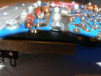
NEWFLASH! Is this what caused the whole darn problem? I just noticed this on the good side..
I am guessing it was never soldered on during the last repair...
I am guessing it was never soldered on during the last repair...
An externally hosted image should be here but it was not working when we last tested it.
An externally hosted image should be here but it was not working when we last tested it.
Attachments
and yes it was not 12v but 120v..
Here are some more pics...
This is the BBCode for your photo for message boards and communities.
You can barely see the shrink tubed grey wire here on the right side (from the front)
Not burned as bad as the right side...
Also; that bug looks suspicious.. looks like it might be a terrorist.
Here are some more pics...
An externally hosted image should be here but it was not working when we last tested it.
This is the BBCode for your photo for message boards and communities.
An externally hosted image should be here but it was not working when we last tested it.
You can barely see the shrink tubed grey wire here on the right side (from the front)
An externally hosted image should be here but it was not working when we last tested it.
Not burned as bad as the right side...
An externally hosted image should be here but it was not working when we last tested it.
Also; that bug looks suspicious.. looks like it might be a terrorist.
Back to your transformer question:
Right side: Yellow solid ; grey (I think solid, its short) and black. Yellow goes to the switch.. so its power. And black goes to one of the power cord wires; and the grey goes nowhere. On the otherside. 2 wires go to the rectifier.. I cant tell what color they are (see photos) kind of greyish.. and a blue/wh which goes to the bar of the caps and a blue/black which goes to the terminal strip..
does that answer?
Also; the burned resistor.. shall I remove it? I think it read about 10 ohms?? I mean before I test that side (I resoldered that resistor to the power transistor that was loose)...
I have gotten one thing done.. dusted the entire inside with a paint brush and vacum. I feel much better now.. oh and the bug carcass is history.. I think he did it.
Also; I would like to point out that I do NOT see evidence that that solder joint got hot and it just pulled away.. it looked very clean.. the photo is pretty accurate.
update.. the right channel seems to be working perfectly.. No DC at the input.. been playing it thru and really crappy speaker for about 10 minutes.. I'll let it got for a bit but I think its good.
Soooo.. I definately want to fix it now if I can manage it.. Sounds really good even thru a horrible old sony jbl speaker.. you can hear the speed of the amp.. SWEET..
Gotta find a buncho resistors; caps; etc...
Soooo.. I definately want to fix it now if I can manage it.. Sounds really good even thru a horrible old sony jbl speaker.. you can hear the speed of the amp.. SWEET..
Gotta find a buncho resistors; caps; etc...
Okay... need to okay if its okay to order the 2n5876 here:
http://store.americanmicrosemiconductor.com/2n5876.html
and the 2n5878 here:
http://www.mouser.com/search/productdetail.aspx?R=2N5878virtualkey61000000virtualkey610-2N5878
Thats the only place I could find the 2n5876's.. so far..
Whats a good source for resistors? Radio Schack?
-Joe
http://store.americanmicrosemiconductor.com/2n5876.html
and the 2n5878 here:
http://www.mouser.com/search/productdetail.aspx?R=2N5878virtualkey61000000virtualkey610-2N5878
Thats the only place I could find the 2n5876's.. so far..
Whats a good source for resistors? Radio Schack?
-Joe
Just got back...
Good Job!!!
You can source pretty much everything you'll need between Digikey and Mouser.
Since you're ordering from Mouser anyway, might as well order the resistors from them also if they have them.
See if you can find Mills 3 watt wirewounds in the .68 value from either place.
I'd change all of them on both channels if it were me...
I'd also replace all of the small resistors on the boards with Dale RN55 series - Mouser has them... Your boards have all carbon composition resistors and they are most likely out of tolerance due to age.
You'll also want to order Panasonic FC series small caps for the boards. Just replace all of them on each channel.
One other thing - you might consider calling New Jersey Semiconductor to see if they have both of the outputs as original Motorola parts. You will have to look up their number. If they do, they will most likely also have them from the same lot if you ask them. Lastly, if they don't have them, see if they can recommend someone who does.
Once again, good job so far!!!
Hey Steve,
I just wanted to say thanks for all your help.. even if this is as far as I get I cant thank you enough for your help.. I actually have a pretty good idea how to fix this thing now!
I am going to try and order up everything today/tonight.. my plan is to fix the broken channel and then upgrade all the components you suggested on the other side.. As far as I can tell this amp sounds sweet.. so I am excited to continue on and get her going again..
thanks for your patience... its due to people like you that I do not lose faith in the human race!
Same to the others that have given me advice.. especially Mr. Pass.. the only downside is I am going to want to take on one of your DIY projects.. and I really dont have time!
- Home
- Amplifiers
- Pass Labs
- Repair question re: threshold 400a