A family member recently gave me a dead Creek 4240SE integrated amplifier. The unswitched outputs were inadvertently grounded together. I found the power supply fuses were blown when I opened up the case. When I replaced them, they quickly blew again (less than 2 seconds). I have contacted Creek to try to get a schematic (the sent me one for my old 4140 a few years ago), but I have not been able to get them to send me one for the 4240, so far.
I am pretty new to the DIY audio world (one Millet Max headphone amp build under my belt), and I don't have much of an electrical engineering background, so I am looking for any help I can get on diagnosing the problem(s) and repairing them. I am an engineer, however, and I have access to most of the tools I could imagine needing (DMM, O-scope, etc). This is not an urgent project, but I am hoping to learn a little about amplifier design in the process. If anyone has the schematic for this amp and can share it, or has any tips on where I should start with debug, I would appreciate the help.
Thanks in advance!
I'd say it is likely that your output transistors have failed short circuit as a result of the original short on the output, before the PS fuses blew. Now you have most likely got a permanent short on the output which is why the fuses blew again.
Check the output transistors for shorts, as a first step") There may be other collateral damage as well, but that's a starting point.
There may be other collateral damage as well, but that's a starting point.
Tony.
Check the output transistors for shorts, as a first step
There may be other collateral damage as well, but that's a starting point. Tony.
Last edited:
Thanks for the quick response, wintermute.
Without a schematic, (OK, probably even with one) I'm a little lost on which are the output transistors. The board layout is not completely straight-forward to me. I will take a look at it and see what I can figure out. I'll report back with what I find.
Without a schematic, (OK, probably even with one) I'm a little lost on which are the output transistors. The board layout is not completely straight-forward to me. I will take a look at it and see what I can figure out. I'll report back with what I find.
if you have access to a variac, that can be really useful when trying to troubleshoot a power amp with a short circuit. connect the variac output to the amps power connector, start with the voltage at zero and turn it up slowly while measuring the input current. you might only be able to turn up the voltage a little bit before approaching the current rating of the PS fuse. if you run it with low line voltage and keep the current low enough, you will have a chance to probe around and figure out what's happening without keep on blowing stuff up. I agree that it's likely the output transistors are blown, but if there's still something else wrong you might just replace all the blown output transformers, then turn it on and blow them all again because something else is still wrong. happened to me before.
-Joel
-Joel
without wanting to sound too funny I'm not familiar with the amp, Id say the big ones mounted on the main heatsink(s)
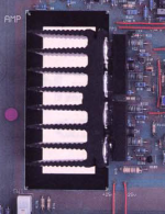
I just did a search and found an image of the guts of the amp on creeks website Creek Audio's Old Products :
the ones mounted to this heatsink in the image below.. it is very hard to tell from the picture if they are chips or transistors with some sort of heat spreader on them.
edit: ok I looked at the other pdf in the zip file and it says it has mosfet driver and output transistors, so they aint chips
Tony.
Attachments
Last edited:
Looks rather similar to 4330 (see attachment). In case you will be replacing the output MOSFETs, note they must be "logic level", e.g. Vgs(th) should 1..2V, not 4V as non-logic-level MOSFETs (such as IRF610) have. The ones used by Creek may not be available, but IRL540 seem to work well in 4330. There is no real replacement for ZVP3310, but those are available.
BTW, I believe 4330SE simply had a bigger power transformer than non-SE. The schematics were identical.
BTW, I believe 4330SE simply had a bigger power transformer than non-SE. The schematics were identical.
Attachments
Thanks everyone for the help!
A few comments:
There was a definite shorting "event" on this amp that probably caused the failure. The thermal compound is a little dry, but not too bad. I will replace it when I replace the FETs.
There are 6 devices mounted to the heat sink. They are divided into left and right channels. 2 for each channel are TO220 package BUK555-100B logic level power FETs. I tried measuring resistance from source to drain and got the following:
(Right Channel)
Q111 - Starts off at around 125kOhm and levels off at around 42.5kOhm
Q112 - Starts off at around 146kOhm and levels off at 9.1 kOhm.
(Left Channel)
Q11 - Starts off at 0 Ohm and levels off at 18.6 Ohm
Q12 - Never really levels off, but is in the 15MOhm range.
The other two devices are TO-92 packages (Q8 and Q108). I can't read the markings on these because the flat surface of the package is against the heatsink which I haven't removed yet.
So with my novice level experience, I'm not sure if the transients I am seeing in the measurements are normal or not. I am just measuring with a cheap DMM at this point. However, from what I am seeing, I am going to guess that the Left Channel FETs (Q11 and Q12) are blown.
So now for more questions:
1) From my previous hybrid amp build, I understand that matching some transistor devices is important for sound quality. Is this important for this case? (I am assuming the answer is yes) If so, how do I go about matching them (what measurements should I take?) I expect I will replace all 4 FETs.
2) I understand that properly biasing the FETs is important. It would appear that the only adjustment here is via PP1 and that this should be adjusted so that the voltage drop across R22 is 11-12 mV based on this schematic. (Is this correct?) I have V1.3 board, so I probably need to research this a little more.
3) What else should I be testing before I make repairs?
Again, many thanks for answering my novice questions. If anyone needs any mechanical or thermal questions answered, I'll gladly return the favor!
So after a little more investigation, it looks like 2 of the 4 output FETs are bad (one on each channel). I am ordering replacements (IRF540N per x-pro and alexcp). I haven't found anything wrong with any of the other parts. There are a number of differences in resistor values and even a few of the other active parts between the V1.3 board I have and the V1.0 and V1.2 schematics. Still not sure if this will affect the bias settings. I'll report back after the repair is made.
Quick update for anyone interested...
I replaced the 4 output FETs with IRF540NPBF and refreshed the thermal grease at the same time. After letting it heat up and adjusting the bias, it looks like everything is working. Thanks to everyone for helping me out, (including x-pro for the off-line help).
I replaced the 4 output FETs with IRF540NPBF and refreshed the thermal grease at the same time. After letting it heat up and adjusting the bias, it looks like everything is working. Thanks to everyone for helping me out, (including x-pro for the off-line help).
I know this thread is eight months old but I hope some folks are still subscribed. I am working on a 4240 (V1.2) and could use some help. I got a lot out of wutzacircuit's writeup but my problem could be slightly different. My background is in tube amps so I am still feeling my way with units like this.
The symptom with this one is that following a power surge (lightning strike) when turned on the amp immediately produces a steady hum, not affected by the volume control. It sounds like DC on the outputs, and sure enough there is 7 vdc on each speaker out, after running for around 3 sec. I quickly shut it off because the two small 30Ω resistors, R31 and R34 in this 1.0 schematic, begin to smoke. The fuses don't blow, but it is as if these resistors are trying to act like fuses.
I received the amp with the burnt resistors, replaced them and the new set immediately got smoked, so I presume the problem is either up- or downstream form there. Next I removed the fuses (which on this amp are located right after the PT secondary as in the 4330 schematic) and got good 50+ vac from the transformer.
From this description can anyone here suggest any additional tests I can do to pinpoint the problem? I imagine the output transistors will need replacement, but my concern is that, as JoelS points out, something else could be wrong. I do have a variac, so I could apply low voltage but I don't really know what to measure for.
Thanks,
RWood
R31/34 are simply isolation resistors for the input and VAS stage of the amplifier. If these are smoking then something in this section is drawing a lot of current. I'd use a bulb or variac to power up the amp, and then check the voltages at the points mentioned on the schematic.
Another suspect here is IC1, the servo opamp. This may well have died. It's worth checking, although R25 and R32 would also be getting hot. If it has died, check the supply voltages - it's possible ZD1 and/or ZD2 are dead.
As the input+VAS are mostly low cost TO-92 parts (Q1-Q7), it might simply be worth shotgun replacing them. Check ZD3 too as it is an important voltage reference for the current sink that feeds the input stage (Q1 and Q2).
The problem with lightning strikes is that they are so destructive, they may well have zapped everything.
Thanks jaycee; big help.
Luckily all those parts are available and cheap, so I can can go ahead and get them all. If I'm reading it right, Q1 - Q7 are for one channel, Q101 - 107 would be for the other channel.
The zeners are not as descriptive. Is 15V all I need to know to get ZD1 - 3?
I am a little unclear on how to check voltages when I have reduced the line voltage via variac. Does the DC voltage drop proportionately so that if I were running, say 25% of normal, my DC should be 8.75 instead of 35? Or am I just looking for any voltage where it should be, and make note of where there is none?
RWood
Any appropriate 15V zener diodes should work, yes. The main key will be the casing type. I'd suspect 1.3W zeners so something from the BZX85 series should work. If in doubt try to measure the length of the main body and the diameter.
You make a good point about the voltages. I think before doing voltage testing you'll need to start pulling parts and testing for dead shorts. I'd go for the zeners first, then the transistors. These will need to be pulled to be measured. Resistors should test in circuit ok.
You make a good point about the voltages. I think before doing voltage testing you'll need to start pulling parts and testing for dead shorts. I'd go for the zeners first, then the transistors. These will need to be pulled to be measured. Resistors should test in circuit ok.
Thanks for the input and the logic....... I'm including the zeners in the parts order anyway since they're cheap.
I'll report back when I've got some new parts installed.
Btw, Luke Creek came through with a schematic. It's the same version 1.0 as above, not the 1.2 that matches my board but I'm hopeful that it will be close enough for these repairs. I do appreciate his response, though; I had emailed the company before finding this very helpful thread.
RWood
Well, another 4240 is back in service! It sounds great, too. Thanks, everyone, especially jaycee for steering me in the right direction. I installed all new Q1 - 12 for each side plus IC1 & 2, ZD1-6. And of course new resistors to replace those that were burned out. I also changed out the filter caps, just for good measure.
I had tested it a few times throughout, and got no joy until doing Q1-8 on both channels, then it jumped. As yet I have not tested each individual Q to see if there was one culprit.
I do have a question, though, [FONT=Arial, Helvetica, sans-serif]about a pair of resistors: R27 and the corresponding R127 for the right channel, values for both are 300K. On this amp, both these resistors had been cut out after originally having been installed. They were just gone (save for the little stubs of their leads)! So, my question is were these resistors intentionally removed from the circuit to improve it? Or were they removed maliciously (possibly by the repair shop that quoted this repair but did not wind up getting the work)? The amp had also been in for service once in the 1990s.
As I mentioned, I am more familiar with tube circuits but took this project on for a friend so I am not well versed enough to know the function of R27 & R127. My WAG would be feedback circuit. Incidentally, on the V1.0 schem the value of these resistors is 270K. I had neither on hand but did use 220K, and as I said it sounds really good to my admittedly mid-fi ears.
I appreciate your thoughts here before I button it back up and send it home. Thanks,
RWood
ps Here is the V1.2 schem, as provided by Robert C by way of Alex N:
[/FONT]
Attachments
- Status
- This old topic is closed. If you want to reopen this topic, contact a moderator using the "Report Post" button.
- Home
- Amplifiers
- Solid State
- Repair help requested - Creek 4240SE