Hi Joren
I have not yet been able to do the mod of attaching a TDA1541 to the SAA7000 yet, but I have done some listening tests between a Marantz CD94Mk II (CDM1 and 2 TDA1541 S1) and a Philips CD 202 (CDM0 & TDA1540). The Philips has been modified by upgrading all capacitors, removing the baseplate and placing it on wood. The Marantz is completely standard but with headphone output disengaged.
Sound wise I found the Marantz a bit dark but very smooth sounding. To my ears the Philips sounded more dynamic and open, with a slightly larger soundstage. This increase in soundstage is probably due to placing the player on wood. I also preferred the sound of guitars on the Philips. Please note there are many confounders in this comparison.
An ideal comparison would be to construct the TNT audio 1541 dac section only and use the original power supply and output stage from the CD player. You will have to attenuate the - 17V & –7V to –15V & -5V respectively which can be done using a resistors or small inductors. Pin 22 of the 1540is the output, if your dacs are on sockets you can simply remove them and connect:
pin 6 of 1541 to pin 22 of right channel’s 1540’s socket
pin 25 of 1541 to pin 22 of left channel’s 1540’s socket
This should not be too difficult, but you will need the datasheets for the above chips.
I hope this helps
Regards
Richard
Hi Richard,
Thank you very much for the answer.
I do not know the marantz 94 and the philips cd202 but I suppose they have different output stages etc. A good comparison would be difficult then. Your observation does coincide indeed with other comments I read about the 1540 : good for electric guitars, tube-like... HAH, that's why I bought the CD104, the tubes I mean, not the guitars...
If I understand correctly the SAA7030 does the oversampling so SAA7000 to DAC would mean no OS. Also someone mentioned the SAA7030 introduces additional jitter.
I know I should do the test myself (and perhaps I will when I get my second 104 from marktplaats=ebay) but again..... someone might have tried before and could have good arguments not to go there.
Jeroen
Hi Jeroen
Your right the SAA7030 does the oversampling its datasheet also says it "improves the signal quality for digital to analogue conversion".
If your worried about jitter you can add a Kwak Clock (KC). All other after market clocks don't offer the 4.0 MHz crystal. With some help I managed to transplant the original crystal to a KC and clocked the SAA7000 IC, pin 8 is the input. This yielded some good results, not a huge difference on this player but there was more decay to instruments. I managed to get a more substantial improvement by building a better power supply for the KC.
Cheers
Richard
Hi guys,
I always wanted to build non oversampling dac and recently I got old philips CD and after reading this text I removed SAA7030. Sound improvements are unbeleveable, everytime when I listen it i'm wondering is it possible that CD sounds so good. I can send pictures of modification inside CD, but there is no need, if someone wants to do modifacation just follow instruction from first page of this tread. Only difference is don't disconnect pin 6 (clox) of saa7000 because it is used for controlling motor in player. For 5v pin 16 connect to pin 18 (and cut it from ground before that") )
)
Post your impressions!!
Regards.
I always wanted to build non oversampling dac and recently I got old philips CD and after reading this text I removed SAA7030. Sound improvements are unbeleveable, everytime when I listen it i'm wondering is it possible that CD sounds so good. I can send pictures of modification inside CD, but there is no need, if someone wants to do modifacation just follow instruction from first page of this tread. Only difference is don't disconnect pin 6 (clox) of saa7000 because it is used for controlling motor in player. For 5v pin 16 connect to pin 18 (and cut it from ground before that
)Post your impressions!!
Regards.
JeroenR said:Thanks for sharing experience.
I also want to try these mods but also want to add a clock. I have the manual and see that the 4MHz clock is feeding the 7000. Can I feed pin 28 on the TDA1540 also with an external 4MHz clock? (tent XO 8MHz and 74HC74)
Jeroen
Have you seen this ?
http://www.geocities.jp/tochey_2000/cdp15.html
Some interesting pictures. If you shorten the url to
http://www.geocities.jp/tochey_2000
and navigate the CD34 links. google offer a Japnese to english translator which might help
Schematic?
Hi Richard,
Any schematic of this new power supply? I am most interested.
Richard said:......... I managed to get a more substantial improvement by building a better power supply for the KC.
Cheers
Richard
Hi Richard,
Any schematic of this new power supply? I am most interested.
Hi Elso
Sorry I don’t have a schematic to post, but essentially the power supply is as follows:
After the diode bridge (I’m using 1 bridge per rail as the transformer has 2 secondaries) there are 3 x 3300uF caps, followed by LM 317 and 337 type regulators, with protection diodes. After the regs I have a 2200uF cap, bypassed with a .022MKP. Nothing special but I might add a common mode choke after the 1st 2 3300uf filter caps.
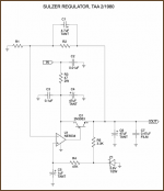
I plan to build a Sulzer low noise power supply next. See attachment
I also have a query. I have had excellent results with your version 7 clock in 3rd and 4th generation Philips and Marantz players (11.98 MhZ) . However, after I installed it into my CD 202 (SAA7000 4.42 MHz), apart form the usual gains I seemed to have lost a bit of bass. I did not use any resistor between the clock output and the SAA7000. Any thoughts or advice appreciated.
Cheers
Richard
Sorry I don’t have a schematic to post, but essentially the power supply is as follows:
After the diode bridge (I’m using 1 bridge per rail as the transformer has 2 secondaries) there are 3 x 3300uF caps, followed by LM 317 and 337 type regulators, with protection diodes. After the regs I have a 2200uF cap, bypassed with a .022MKP. Nothing special but I might add a common mode choke after the 1st 2 3300uf filter caps.
I plan to build a Sulzer low noise power supply next. See attachment
I also have a query. I have had excellent results with your version 7 clock in 3rd and 4th generation Philips and Marantz players (11.98 MhZ) . However, after I installed it into my CD 202 (SAA7000 4.42 MHz), apart form the usual gains I seemed to have lost a bit of bass. I did not use any resistor between the clock output and the SAA7000. Any thoughts or advice appreciated.
Cheers
Richard
Attachments
Hi Elso
Where on the 5V supply would be the best place to put this cap?
Parallel to C16 and C17, or immediatly after Q2 and Q3.
You also may find the link useful. It is for a sulzer regulated PSU for a clock. Look under Marantz SA8260 mods and then 2/3 down the page. Pics and schematic are on the left of the page.
http://www.winebase.com.au/audio/
Richard
Richard said:Hi Elso
Where on the 5V supply would be the best place to put this cap?
Parallel to C16 and C17, or immediatly after Q2 and Q3.
You also may find the link useful. It is for a sulzer regulated PSU for a clock. Look under Marantz SA8260 mods and then 2/3 down the page. Pics and schematic are on the left of the page.
http://www.winebase.com.au/audio/
Richard
In my clock the 12,000µF replaces the 1µF caps.
I have tried all kinds of regulators, including Schulzer and Jung. My feelings are the latter 2 are not suitable for a clock supply, in other words not better than the TL431 scheme I am using in version 7. But of course you can try yourself.
/to rfbrw:
Hi, I tried removeing the saa7030 in my Philips CD-150 and just connect the following with wire.
Pin20 DLCF to Pin3 DLFD.
Pin17 DRCF to Pin10 DRFD.
Pin18 /CLCF to Pin6 /CLFD.
Pin21 STR1 to Pin7 LAT.
I turned on the player and it produced the most wonderful noise I have ever heard from a cd-player ;-))
When removing the saa7030 are these for connections the only ones to passthrough? Or do there need to be more components removed or connections made?
Thanks in advance.
Regards,
Ramon
D.A.R.R.Y.L. said:/to rfbrw:
Hi, I tried removeing the saa7030 in my Philips CD-150 and just connect the following with wire.
Pin20 DLCF to Pin3 DLFD.
Pin17 DRCF to Pin10 DRFD.
Pin18 /CLCF to Pin6 /CLFD.
Pin21 STR1 to Pin7 LAT.
I turned on the player and it produced the most wonderful noise I have ever heard from a cd-player ;-))
When removing the saa7030 are these for connections the only ones to passthrough? Or do there need to be more components removed or connections made?
Thanks in advance.
Regards,
Ramon
Does the cd150 have a saa7000? Did you put it in 14bit? (pin 16 with 1K to 5V).
I got that "sound" when I just miswired the 7030-bridge, I think I mislayed the STR1->LAT.....

Hey Jeroen,
It has a saa7000.
But I left the tda1540 dual, so 16bit is not required.
Or when you remove the 7030 entirely, the SAA7000 switches automatically into 16-bit mode?
All four connections where correctly made, i double checked.
Or are there alternate connections te be made when SAA7030 is removed and the SAA7000 is, by bridging these four connections, directly connected to the DAC's?
D.A.R.R.Y.L. said:Hey Jeroen,
It has a saa7000.
But I left the tda1540 dual, so 16bit is not required.
Or when you remove the 7030 entirely, the SAA7000 switches automatically into 16-bit mode?
All four connections where correctly made, i double checked.
Or are there alternate connections te be made when SAA7030 is removed and the SAA7000 is, by bridging these four connections, directly connected to the DAC's?
See this thread : http://www.diyaudio.com/forums/showthread.php?s=&threadid=32591&perpage=10&pagenumber=16 posts 157 and 169
For the CD104 : the 7000 was set to 16 bit -> 7030 accepts 16 bit and outputs 14 -> 1540 takes 14 bit.
The saa7000 will not switch automaticaly from 16 to 14.
You will not be disappointed after this change.
D.A.R.R.Y.L. said:So I have to disconnect pin 16 from ground on the SAA7000 and connect it to pin 18? It will then have +5v on pin 16? And hence the SAA7000 wil output 14bit?
Is this correct?
Is the 1k picky or is other value ok?
1. yes
2. 4.8V
3. yes but with 1K in between
4. yes
(5. remove sa7030 and offer this piece of antique on Ebay)
I use a (about) 800ohm resistor.
Let me know if you need datasheets.... and if you like what you hear after the mod.
- Status
- This old topic is closed. If you want to reopen this topic, contact a moderator using the "Report Post" button.
- Home
- Source & Line
- Digital Source
- remove saa7030