Petter,
unfortunately, if I make the schematic the way you suggested, then people could not use the volume controller for single ended inputs. (I think?)
The relay driver chips we used do indeed have flyback diodes!")
Also my last post was wrong, it is not a "stepped ladder relay board", it is a "series type stepped attenuator." to allow the pre-amps to see a constant impedance.
When the power goes out, the inputs are disconnected from the ouputs , which brings up another serious issue, is it O.K.
to have the output lines floating when the power goes out?
Or do I need to tie them to ground?
Also as far as the switching delays. Thats no problem, since we control them with a microcontroller.
Thanks for your comments,
-Craig Beiferman
unfortunately, if I make the schematic the way you suggested, then people could not use the volume controller for single ended inputs. (I think?)
The relay driver chips we used do indeed have flyback diodes!
Also my last post was wrong, it is not a "stepped ladder relay board", it is a "series type stepped attenuator." to allow the pre-amps to see a constant impedance.
When the power goes out, the inputs are disconnected from the ouputs , which brings up another serious issue, is it O.K.
to have the output lines floating when the power goes out?
Or do I need to tie them to ground?
Also as far as the switching delays. Thats no problem, since we control them with a microcontroller.
Thanks for your comments,
-Craig Beiferman
Hi Petter,
Thanks for the suggestions. Craig and I will meet today to discuss all of the options.
Unfortunately, it may come down to board space, and cost. Relays cost from USD$2.00 to USD$6.00 ea. We are already at close to 70 relays... This version may cost a bit more than we anticipated.
What are people willing to spend on a ladder relay controlled volume control?
There are some smaller DPDT relays (Omron G6H) that we are looking at. I am not sure if we can use a generic relay configuration and meet size requirements. We could go back to a two relay board configuration. This might make a single ended solution less costly. We also want this version to accomodate transformer based volume controls.
I sure hope that we have enough I/O lines... I hope not to change the micro board, but we might have to add some I/O expansion via SPI or I2C...
Keep the suggestions coming. I apologize in advance if we don't end up incorporating all suggestions.
Best Regards,
Dale (and Craig)
Graig and Dale,
Even if I don't totally agree with Petter's attenuator layout, it can be made to work with single ended inputs by shorting the - line to ground before and after the - series resistor.
I still much like your approach to the design. Shorting the + and - lines like he suggests only gets rid of the common mode noise.
On later versions of the design I would like to see a totally symetrical design, much like the Levinson pre-amps.
Regards,
Jam
Even if I don't totally agree with Petter's attenuator layout, it can be made to work with single ended inputs by shorting the - line to ground before and after the - series resistor.
I still much like your approach to the design. Shorting the + and - lines like he suggests only gets rid of the common mode noise.
On later versions of the design I
would like to see a totally symetrical design, much like the Levinson pre-amps.Regards,
Jam
Attachments
Advantages of shorting between phases:
1. Any noise or offset on the ground is masked out. You would not believe how much crap there is on the ground -- and some of it may even come from the microcontroller you are using
2. Half the number of relays are required -- 1 mon0 relay per bit per channel.
3. Using series switch element makes it possible to make do with less than 8 mono relays per channel to get more than 8 bits resolution (high/low range). 8 Bits is more than enough.
4. The sound must surely be better since signal never really passes through any relay for the attenuation relays. Only the shorted stuff ever passes there.
5. As noted, this setup can be used for single ended inputs as well either in bulk mode (all inputs or none by single shorting jumper or swith to ground) or by having such a jumper/switch to ground for each individual input
6. Topology choice: Not going to ground gives you the flexibility to place the volume control at a different DC voltage then ground. This further allows 2 stage DC coupled amplification with the volume control between stages as I have posted here http://www.diyaudio.com/forums/showthread.php?threadid=3625&perpage=15&pagenumber=5 and http://www.diyaudio.com/forums/showthread.php?threadid=3626
Also, in software it should be possible to use pre-scaling so that one can adjust the sensitivity of each input to be as loud as the other regardless of how it is fed.
Since you guys are going overboard on this, may I just congratulate you on this effort and choice of switching element. My measurements indicate that relays are so much better than transistors, FET's, JFET's etc in the various topologies I have tested (including Wayne's Passlabs mode) -- we are talking like 20-30dB difference in performance when moving to relays!!! I could not believe it when I saw it.
Also, for the totally far out version, one might want to add an option for multichannel setup (I will soon be using digital crossover and need 6 channels of volume control for my stereo set). Perhaps it is even possible to make el-cheapo units by slaving external "digital potentiometers" for the lesser channels in a home theater setup?
And for ultimate in reliability and signal integrity, allow the use of mercury wetted reed relays, at least for the series elements (input selectors and possibly scaler from my suggested drawing). These are very expensive, though. The performance of regular el-cheapo relays is very very good as well. Consider using the SIL form factor units to save space and also consider if Reed relays will help with longevity of unit. Also try to get low audible mechanical noise units.
Great work guys!
Petter
Petter,
You do make a convincing arguement. Especially the signal not passing through any contacts (source of distortion).
My main concern is presenting a constant impedence to the source. Maybe a buffer before the volume control. (this might not be a problem with most solid state devices)
What value of series resistor do you propose (10 to 20k?)
Regards,
Jam
L+R, L-R
I probably haven’t stared at the diagram, or read enough of the thread yet to know if I should be asking this question.
I’ve built a handful of relay based balanced input selectors and also a few routers for sending feeds to different amplifier and speaker combinations.
For professional applications I found that engineers would often ask me to include: L only, R only, L+R, and L-R and dim (lowered volume as apposed to mute) applications.
L+R and L-R were particularly useful when chasing phase issues in source material. I remain amazed at how many times the ‘Pros from Dover’ could screw this one up.
Dim is a nice feature for when someone interrupts you, but you don’t want to full out mute the sound.
At the risk of feature creep, I'm curious if other audiophiles would be interested in these features too.
OK,
I just finished reading the thread.
A dim function should be implamentable in software. It should also be possible to user select the DIM level.
I have been wondering about your approach to software. Are you going to be open source? A breadboard section and the ability to add a function or two (like my L+R, L-R thing...) would be nice.
I also like the idea of being able to trim each input level.
I agree with the input shunting. I think I saw a sketch that showed the gnd being switched too. This strikes me as a bit of over kill. If there is anyone out there still using things like an Ampex A440 1/2 track machine, dropping the lifters during shuttle can send out peaks in excess of +30dB with loads of harmonics. Hell yah, that’ll bleed through a Coke bottle as well as toast a little 1/8 watt resistor. Depending on which R/P amps you have with your Ampex shorting 2-3 or 2-3-gnd could cause a bit of smoke, but I haven’t looked at the schematics for a number of years so cant say for sure. I guess my point is that if some one is fanatical enough to want this sort of clean audio path, some of their modern audio gear might be > 30years old. If the board had a space where I could drop in my own shunts as needed, that would be cool.
I'm not sure that I followed the resolution of what happens if power is lost. I live in a town with some unfortunately high RF fields, unexpectedly having the inputs to my amp go open, even assuming that CMR is working and that all the relays (inputs and attenuators) de-energies simultaneously, doesn’t feel too friendly. It at least one relay in each channel could be reversed for fail-safe operation; I'd feel a lot better.
I'm starting to feel like I should get my order placed. I still need to work out the social impact and finances with my highly significant other.
I would guess that I might be the only person who would prefer a wired remote over IR. If your planning on IR emulation for tactile controls, I would assume that I could replace the IR section with an RS-422 diver/receiver pair to remote the front panel. This of course would use a little bit more of that breadboard space too.
Hello,
At this point I am a bit overwhelmed by both the responses and all of the different ideas presented. I think that it is time for Craig (DipChip) and I to get together and sort out everything. We will try to address fail-safe issues at turn-on/turn off.
A couple of points though.
Ground switching is useful to eliminate any ground loops between sources. Of course ground contamination is another potential concern.
Our digital ground is in no way connected to the analog grounds.
Many of the "programming" features will only be available with the LCD/keypad. This would include the "DIM" setting. Other features may include input naming, key/remote repeat rates, power up options (mute, dim, last input, etc...)
Of course, for those so inclined, the board features a ICD2 interface, or one could use an external programmer to modify the code. We are planning on posting it at our web site.
For a wired remote, one would have to "spoof" the keypad commands that come out of the LCD module. At this point, we will only be offering an IR interface with both the Sony and RC5 (Philips) protocols.
The IR interface is a standard 40KHz de-multiplexor that outputs a digital signal to the PIC INT line.
The switch inputs just bring an input pin low. I do de-bouncing in software.
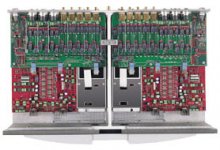
The prototype microcontroller board has arrived
So far, there are a couple of spacing issues (switches too close to LEDS on panel), but otherwise, the board is functioning. I do have some small issues with the mechanical encoder interface. I may be getting too much bounce. I have not looked at the signals with a scope yet.
I'll take some photos tomorrow.
Based on the new relay board, I will need to add some more I/O capability. Probably will add an I/O expander or another PIC.
We should get the Aleph type relay board tomorrow. Then the real fun begins...
Craig is the analog expert, I do the digital stuff...
Dale
At this point I am a bit overwhelmed by both the responses and all of the different ideas presented. I think that it is time for Craig (DipChip) and I to get together and sort out everything. We will try to address fail-safe issues at turn-on/turn off.
A couple of points though.
Ground switching is useful to eliminate any ground loops between sources. Of course ground contamination is another potential concern.
Our digital ground is in no way connected to the analog grounds.
Many of the "programming" features will only be available with the LCD/keypad. This would include the "DIM" setting. Other features may include input naming, key/remote repeat rates, power up options (mute, dim, last input, etc...)
Of course, for those so inclined, the board features a ICD2 interface, or one could use an external programmer to modify the code. We are planning on posting it at our web site.
For a wired remote, one would have to "spoof" the keypad commands that come out of the LCD module. At this point, we will only be offering an IR interface with both the Sony and RC5 (Philips) protocols.
The IR interface is a standard 40KHz de-multiplexor that outputs a digital signal to the PIC INT line.
The switch inputs just bring an input pin low. I do de-bouncing in software.
The prototype microcontroller board has arrived
So far, there are a couple of spacing issues (switches too close to LEDS on panel), but otherwise, the board is functioning. I do have some small issues with the mechanical encoder interface. I may be getting too much bounce. I have not looked at the signals with a scope yet.
I'll take some photos tomorrow.
Based on the new relay board, I will need to add some more I/O capability. Probably will add an I/O expander or another PIC.
We should get the Aleph type relay board tomorrow. Then the real fun begins...
Craig is the analog expert, I do the digital stuff...
Dale
Da5id4Vz,
Please excuse my ignorance, I'm pretty new to the audio world. Can you please describe in more detail what you mean when you want L, R, L+R, and L-R
I guess the L-R threw me!
Also, if you don't use the LCD module, there is a level shifted RS232 on board. I don't know if this will help you or not to get a wired remote. we currently don't have plans for rs-422, and we currently used all of the microcontrollers pins.
version 1 of the input/volume relay board is due to arrive tommorow. Yippee!
Dale built up remote board and it looks very good. He downloaded the software, and was actually controlling the LEDS with a universal remote on the very first download. Amazing!
Dale or Craig,
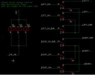
I tried to look through the schematic but cannot tell from the jpg.
In the case of mixed RCA and XLR input, in the presence of a balanced line stage, what do you do with the cold pin when switching to an RCA input? Is it getting switched to gnd or is it going to stay open?
I tried to look through the schematic but cannot tell from the jpg.
In the case of mixed RCA and XLR input, in the presence of a balanced line stage, what do you do with the cold pin when switching to an RCA input? Is it getting switched to gnd or is it going to stay open?
232 works great, I can use that and place the LCD in the remote. This is based on the assumption that after a friend sees the one I build for the living room that he will want one for his music studio. He does a lot of recording and production work and IR remotes typically don’t cut it in that environment.
Guess I should have spelt out my jargon a little more. I was referring to having the ability to:
Solo the Left channel
Solo the Right channel
Sum to mono the left and right channel in phase
Sum to mono the left and right channel out of phase
I'm not sure if these are features that something that most audiophiles would want. I’ve had a number of engineers ask for them for audio mixing and editing applications. Having played with them at work for a number of years, I find I really miss not having them at home, now that work no longer exposes me to nice audio equipment.
I don’t know that any of these things are must have for me. It sounds like what you are doing would give me at least 80% of what I would want for an ideal project. These last 15% I can likely work out my self. I figured it would be interesting to throw some stuff out there and see what other people think.
On the issue of switching grounds... Yikes, grounding could likely be discussed on its own for several weeks.
I like building these things in metal boxes (remember all that RF I was talking about). I’ve built a number of input sectors where I floated GND on both inputs and outputs, and had them work famously. If you never connect the ground, you can’t get a GND loop: one of the nice things about working in the passive world.
Other times I’ve used the far more correct technique of telescoping the GND's. Using this rule, the chassis and signal GND's are mutually exclusive and will only connect at one star point. The signal GND's for chasis interconection will be typicly be conected on the equipment output side, but not at the input side on the other end of the cable. The Benchmark Media guide to clean audio installation does a pretty good job of explaining this.
http://www.benchmarkmedia.com/appnotes-a/caig/caig05.asp
This article advocates voltage-matched systems (low Z out high Z in). The approach works great and their products are excellent. They used to carry a line of interface products aimed at equipment upgrades and modifications. They seem to have given these up in favor of packaged systems. Even still, the web site is fun to check out.
John Watkins also wrote an excellent and concise article on the subject that I read in a periodical a few years ago. Couldn’t find it on google. I'll check and see if he covers much of it in, "The Art of Digital Audio".
Jam,
Constant input impedance is nice to have
Constant output impedance is nice to have
Both are an illusion but you can achieve "a little bit of this".
My recommendation is don't worry + try to get as much of the energy as possible into the next stage. Most volume controls only sound very good at maximum volume setting, and progressively worse as you turn the volume down.
Petter
Da5id4Vz,
I am also assuming that the L+R, and the L-R must be done with a summing amplifier and a difference amplifier? (Is that true?)
If thats true we could probably do this stuff on an external board between the input selection and the volume controller. (Where the pre-amp would go)
If we add more ouput lines on the remote. we'd be able to have additional control for other boards
My last problem is what to do with the shield connectors on the XLR connectors.
From the link you mentioned
http://www.benchmarkmedia.com/appno...caig/caig05.asp
1. Should I add a place holder for resistor R6 to connect the signal grounds to the chassis ground.
2. What about C1 and R3? It looks like they want that outside the chassis?
gratuku,
Currently, this unused line would be floating.
Maybe in order to allow L and R control, we should put a shorting relay before the pre-amp outputs?
After Dale and I work out what stuff we need to add, I'll post the new schematic for comments before I begin the final layout. The board is getting pretty large, but should really be a nice product when we are done.
Thanks for all your advice,
Craig Beiferman
Dale this is great, I'm about to build P1.7 preamp.
Looking at the originally posted (fuzzy) schematic of the relay board, it looks like a single 8 bit output from the controller will set both the Left and Right channels to the same level. How will you control balance with this configuration?
Looking at the originally posted (fuzzy) schematic of the relay board, it looks like a single 8 bit output from the controller will set both the Left and Right channels to the same level. How will you control balance with this configuration?
Dane,
You really want balance control?
I doubt that we will offer a balance mode, but will not rule it out.
At low volumes, the dB differences are pretty big.
We will probably be changing the micro board and I will see if I can spare more I/O.
Here are some proposed micro-board changes based on input so far.
1) Mandatory use of parallel LCD (< $16.00 ea) and available in the blue...
2) Programming features via remote interface
3) Only PCB mounted (will go to small tactile ones) switches will be for mute, select, and bypass
4) Led only for IR comm and maybe power.
5) Rotary encoder PCB mounted for volume control
6) Serial interface could be used for wired-remote (maybe)
Dale
Craig,
to be honest I raised the issue but I don't know how important that is. I think it is. Yesterday, I seemed to understand that the unused inputs would be put to gnd via a resistor? I don't know,
I need to see a schematic, not fuzzy, and think about it...
I wish WE could have a meeting today about this stuff, it would be much more stimulating than having a meeting with my boss and having to listen to her dumb-assed ideas for 2 hrs!
- Status
- This old topic is closed. If you want to reopen this topic, contact a moderator using the "Report Post" button.