I built an amplifier with volume control a 64 step
attenuator.
The attenuator is controlled in binary operation by an IR
remote control receiver+logic circuit. The problem I am
having is that the receiver gets false signal whenever I
switch off a light in the room or change the
fan speed in the room by rotating the fan regulator.
I know fluorescent lamps emits IR light and
sometimes cause such problem, but do not understand
why the fan regulator or the switch cause this. The remote control
unit is powered by standard IE type transformer and
LM317 power supply. I am not attaching the circuit as
I think it is a common problem and should have an
easier solution. Kindly tell me what should I do?
Thanks and regards
Roushon.
Could the problem be that a spike or interference is interfering with the logic rather than the IR section. Any interference to an IR receiver tends to just block it or make it appear less sensitive. It wouldn't cause it to output a code that the decoder recognised.
I suspect your problem is more fundamental, although just what is hard to say. Could be anything from a mains spike getting into the PSU to some weird form of EM coupling via nearby wiring.
I suspect your problem is more fundamental, although just what is hard to say. Could be anything from a mains spike getting into the PSU to some weird form of EM coupling via nearby wiring.
Thanks!
Thanks Mooly for your response. I will try using a spike
guard switch board. Or is it possible to add some kind
of small circuitry on the mains entry point of the amp
to avoid such spike interference? I think this will be a
better solution so that I can move the amp to some other
place without any bother about spike.
Regards
Roushon.
You can add a mains filter but you really need to identify the problem first rather than guess. Could the supply be "dipping" in voltage as a load is switched on ? Maybe larger reservoir caps feeding the supply to the logic would help. Logic circuitry can usefully be decoupled with 0.1uf caps across the supply pins of IC's etc. However "switching off" a light points to a burst of RF energy caused by arcing contacts so a mains filter may help.
Filter vary in complexity, this is a bit extreme but it shows what is involved.
Audio Mains Filter DIY | DMS Audio
Identifying & Solving Mains Supply Problems
Filter vary in complexity, this is a bit extreme but it shows what is involved.
Audio Mains Filter DIY | DMS Audio
Identifying & Solving Mains Supply Problems
I built an amplifier with volume control a 64 step
attenuator.
The attenuator is controlled in binary operation by an IR
remote control receiver+logic circuit. The problem I am
having is that the receiver gets false signal whenever I
switch off a light in the room or change the
fan speed in the room by rotating the fan regulator.
I know fluorescent lamps emits IR light and
sometimes cause such problem, but do not understand
why the fan regulator or the switch cause this. The remote control
unit is powered by standard IE type transformer and
LM317 power supply. I am not attaching the circuit as
I think it is a common problem and should have an
easier solution. Kindly tell me what should I do?
Thanks and regards
Roushon.
What type of IR receiver do you use? If you use an integrated one, it's pretty impossible to get a false puls train that matches the code you are looking for. How do you decode the signal?
jan didden
Thanks a lot
Thanks Mooly and Janneman. I should describe the circuit
a bit. The PS consists of:
12-0-12v 5Amp IE transformer, rectifier, 4700uF+4700uF+
0.1uF+2.2k 2W resistor and then LM317+1uF (tantulum)+0.1uF.
This PS before the LM317 also supplies some other
logic circuits and drives the relays (6) of the attenuator.
All the logic ICs are within 2 inches from LM317 so I did
not add any decoupling directly on the pin of the
IC.
The IR transmitter and receiver consists of the ICs HT12A
and HT12D respectively.
I will check the wiring again and place decoupling caps
directly on the pins of logic ICs.
It is true that the switches produces RF when putting Off
as it causes noise in the TV/Radio speakers. Also
I remember the old desktop computer I had before
used to shutdown in such interference.
Thanks for giving the filter circuit site. I will make it for
safety.
It seems to me there is severe problem in the wiring in
my apartment.
Regards
Roushon.
Worth trying a mains filter I think. You can also suppress each switch with a snubber network. You can buy these ready made consisting of a 0.1uf cap and 100 ohm in series suitably rated for connection across the switch.
If you think the main wiring is dodgy then it's worth getting it checked out properly.
If you think the main wiring is dodgy then it's worth getting it checked out properly.
Think about it. What is the chance that a random spike causes exactly the right code to be output from the receiver/decoder?
The overwhelming possibility is that a spike causes your control systen *after* the receiver/decoder to react. Whether it has anything to do with the power supply is just a wild guess. (You can search for your keys under the streetlamp because there's light there, but if you lost them in another place it's pretty useless") ).
).
So we really need a schematic to say anything intelligent about this.
jan didden
The overwhelming possibility is that a spike causes your control systen *after* the receiver/decoder to react. Whether it has anything to do with the power supply is just a wild guess. (You can search for your keys under the streetlamp because there's light there, but if you lost them in another place it's pretty useless
).So we really need a schematic to say anything intelligent about this.
jan didden
Think about it. What is the chance that a random spike causes exactly the right code to be output from the receiver/decoder?
The overwhelming possibility is that a spike causes your control systen *after* the receiver/decoder to react. Whether it has anything to do with the power supply is just a wild guess. (You can search for your keys under the streetlamp because there's light there, but if you lost them in another place it's pretty useless
So we really need a schematic to say anything intelligent about this.
jan didden
Hi Janneman,
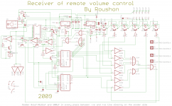
Sorry for the weekend break! We know that the problem is with the
circuitry after the decoder. That is what we are trying to solve. There are several
logic circuits involved and the wiring in the amp cabinet is also under consideration.
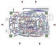
The main receiver/decoder and the relay driver circuit is attached with its pcb design.
(The drawing is not very clean as I was only interested in making the pcb)
The circuit works very well except the occasional interference as I described above.
There is a recent modification to the attached circuit. I am not describing it in great
details as the problem was there before and after this modification.
Thanks and regards
Roushon.
Attachments
Worth trying a mains filter I think. You can also suppress each switch with a snubber network. You can buy these ready made consisting of a 0.1uf cap and 100 ohm in series suitably rated for connection across the switch.
If you think the main wiring is dodgy then it's worth getting it checked out properly.
Thanks Mooly, this is exactly the kind of suggestions I was looking for. I will implement
it and see.
Regards
Roushon.
I built an amplifier with volume control a 64 step
attenuator.
The attenuator is controlled in binary operation by an IR
remote control receiver+logic circuit. The problem I am
having is that the receiver gets false signal whenever I
switch off a light in the room or change the
fan speed in the room by rotating the fan regulator.
I know fluorescent lamps emits IR light and
sometimes cause such problem, but do not understand
why the fan regulator or the switch cause this. The remote control
unit is powered by standard IE type transformer and
LM317 power supply. I am not attaching the circuit as
I think it is a common problem and should have an
easier solution. Kindly tell me what should I do?
Thanks and regards
Roushon.
What kind of error detection/correction are you using? Commercial products I've worked with are often 32 bit units transmitting an 8 bit header 2 times , the second time with the bits inverted. The data is the same story of 2 8 bit bytes, the second with all bits inverted. The bits are modulated onto a carrier, often 38KHz though others are used. The point is to be able to ignore pulsing lights and sun 'noise'.
G²
I am using the same method of communication between the encoder and
decoder using HT 12 A and D ICs as you mentioned. Actually the problem I
am having is something to do with the several logic circuits involved after
the decoder.
Thanks and regards
Roushon
Electromagnetic radiation is playing the trick. If I am not wrong, u have used the transformer for powering the unit. Buy one of the cheapo SMPS ac adaptors/supplies and connect two small (some pF) but X2 type capacitors from mains to the safety earth.
Gajanan Phadte
Edit: Fix .01µF ceramic near each IC, across dc supply.
And this problem is more prevalent when humidity is high.
Gajanan Phadte
Edit: Fix .01µF ceramic near each IC, across dc supply.
And this problem is more prevalent when humidity is high.
Last edited:
Electromagnetic radiation is playing the trick. If I am not wrong, u have used the transformer for powering the unit. Buy one of the cheapo SMPS ac adaptors/supplies and connect two small (some pF) but X2 type capacitors from mains to the safety earth.
Gajanan Phadte
Edit: Fix .01µF ceramic near each IC, across dc supply.
And this problem is more prevalent when humidity is high.
Hi Gajanan,
Thanks for your response and for the
suggestions. I am going to add the mains filter. Due to
some other work I do not have time to open the amp and
make the changes. Will post the result here when it is
done.
It is been a very long time to receive response from you.
I remember your valuable advices regarding pcb design
of the amp.
Regards
Roushon.
EMC is the problem.
Adding decoupling caps to each IC's gonna help.
I would try and lay it out with as much ground as possible, a ground plane would be best, but if not well gridded and power connections, ground being the critical one. I would por ground copper round everything and stich it togethyer with vias.
Both fans and flourecent tubes are a source of noise and spikes tah can cause all sorts of problems with circuits.
Thanks everybody for their helps and comments. I
suspected in one of my posting above that the wiring
of my apartment was not correct. It turned out to be
the case. I just shifted to a new apartment and this
problem of the remote control has gone. I tried to
operate all switches/fan regulator in the room
but there was no interference. Nevertheless I will add a
filter for safety.
Regards
Roushon
Thanks everybody for their helps and comments. I
suspected in one of my posting above that the wiring
of my apartment was not correct. It turned out to be
the case. I just shifted to a new apartment and this
problem of the remote control has gone. I tried to
operate all switches/fan regulator in the room
but there was no interference. Nevertheless I will add a
filter for safety.
Regards
Roushon
Good that it solved the problem and believe me there is no problem in the wiring. Only thing is that one has non-favourable layout.
Gajanan Phadte
Good that it solved the problem and believe me there is no problem in the wiring. Only thing is that one has non-favourable layout.
Gajanan Phadte
I assume that you meant the layout of my remote/amp.
Then I should say something more here regarding why I
suspected the wiring. This building was rewired
few months back. They changed everything. Then
all hells broke out. Several of the residents started
complaining about frequent fuse tripping, crashing of
computers, expensive power supply destruction etc
etc. My computer also started shutting down without
any notice. Also the remote problem as you know.
I agree with you that if the layout
of the remote/amp were best then this remote problem
would not have taken place. But wiring must have severe
problem.
Regards
Roushon
- Status
- This old topic is closed. If you want to reopen this topic, contact a moderator using the "Report Post" button.
- Home
- General Interest
- Everything Else
- Remote control receiver unit problem