FIXED GROUND LOOP!!! I used a ground loop isolator, no more humming.....still very little noise, but ignorable....my problem now is that the preamp isn't producing sound....I'm 100% sure the circuitry is correct, but I don't know what's causing this problem. Could it be that I'm giving my lm 1458 13.86V where I should be giving 15, or is that not too big of a problem
alizawi said:FIXED GROUND LOOP!!! I used a ground loop isolator, no more humming.....still very little noise, but ignorable....my problem now is that the preamp isn't producing sound....I'm 100% sure the circuitry is correct, but I don't know what's causing this problem. Could it be that I'm giving my lm 1458 13.86V where I should be giving 15, or is that not too big of a problem
LM1458 spec sheet I saw appears to suggest minimum of +-11V ("LM1458C" version) or +-12V non-C, max of +_18V. These are guaranteed ratings, it should be stable all the way down to 12.0V, and you are above that so you are fine there.
Take your multimeter and (pull the opamp out if not soldered down, or on the opamp pins if it is soldered) take the V+, V- pin voltage readings to gnd. Another handy tool to have is any cheap little speaker (headphones but you might not want to be wearing them "yet" as some *sounds* could damage hearing) with leads soldered on and pins/needles/whatever as probes on the end of the leads. With this, you can put one lead at gnd and the other at the opamp IN+ and hear signal going in. Likewise you can hear signal output, but remember that it should be a fairly high impedance speaker if the circuit can't drive with a lot of current. IE- don't expect a gain of 5 with a 4 ohm speaker to sound right, the opamp alone can't put out the current required.
If we had a schematic of your circuit, even a good hi-res picture it might help. I've never used LM1458 for audio, is it supposed to be any good for a preamp? You might also break the supply circuit and measure current consumption... if oscillating it would tend to use a lot more current and possibly be getting fairly warm. It shouldn't be very warm at a modest 3-5mA current in normal operation.
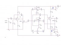
I'll try that andrew...One thing though, If i have headphones, are you saying that I should cut the end of it so I have the wires directly going to the pins? I checked the chip to see if it heated up, but it was not warm at all. Here is a shematic, but ignore the zener diode part, I was going to use that before hte regulators. I think I also have the gain out of the first portion to be 1 instead of 10 as shown in the schematic. I read somewhere that it should work fine with 1.
Attachments
Ok, now things are ugly..... I tried making hte gain 10 again, and the hum returned, then it turned into a screatching/screaming sound that's painful.......and this pretty much damaged the speaker......now the speaker sounds awful... so now this is my test speaker .I took it back to a gain of 1, and the screeching sound was still there!!!! the lm 1458 is a decent preamp chip, I got the circuitry from an audiophile book I found on amazon........
Do you think it would be better if I used the zener diode regulation initially indicated in the author's circuit?
Do you think it would be better if I used the zener diode regulation initially indicated in the author's circuit?
alizawi said:I'll try that andrew...One thing though, If i have headphones, are you saying that I should cut the end of it so I have the wires directly going to the pins? I checked the chip to see if it heated up, but it was not warm at all. Here is a shematic, but ignore the zener diode part, I was going to use that before hte regulators. I think I also have the gain out of the first portion to be 1 instead of 10 as shown in the schematic. I read somewhere that it should work fine with 1.
I was suggesting to take some junky pair of headphones that have zero monetary value, not good headphones, and chop off the plug (or remove the cord entirely, which is more work than it's worth with some. Take the gnd and one channel leads to pins (as probes), but since the cord is unified you'd take jumper wires to get some play inbetween the gnd and each channel. If you want both L & R with probes, ok, but for the basic test it is only necessary to have one channel.
If you had a high-ohm little speaker (again one with no value) lying around that would work too.
Your schematic seems to be missing a few decoupling capacitors, I assume you have some inbetween the 100 Ohm resistors and the opamps? If not, add some.
I haven't done a lot of investigating yet but one person has called the LM1458 "dreadfully slow" and it may be a dual LM741? If it is, I suggest finding another opamp instead, even the 50 cent jellybean chips like TL072/82 would be better.
Is this breadboarded or built up with a lot of work already? My general impression is that it isn't very "hi-fi", that was is gained by having the tone controls is lost (and then some) by putting the signal through 2 LM1458, and one has a rather high 47K feedback.
! said:
I was suggesting to take some junky pair of headphones that have zero monetary value, not good headphones, and chop off the plug (or remove the cord entirely, which is more work than it's worth with some. Take the gnd and one channel leads to pins (as probes), but since the cord is unified you'd take jumper wires to get some play inbetween the gnd and each channel. If you want both L & R with probes, ok, but for the basic test it is only necessary to have one channel.
If you had a high-ohm little speaker (again one with no value) lying around that would work too.
Your schematic seems to be missing a few decoupling capacitors, I assume you have some inbetween the 100 Ohm resistors and the opamps? If not, add some.
I haven't done a lot of investigating yet but one person has called the LM1458 "dreadfully slow" and it may be a dual LM741? If it is, I suggest finding another opamp instead, even the 50 cent jellybean chips like TL072/82 would be better.
Is this breadboarded or built up with a lot of work already? My general impression is that it isn't very "hi-fi", that was is gained by having the tone controls is lost (and then some) by putting the signal through 2 LM1458, and one has a rather high 47K feedback.
Starting with the feedback, I took it down so its not a gain of 10, I'm using a no gain ( 4.7k feedback) just to let the signal pass through...I'm not sure what you mean about tone controls being lost. The book I got this from says this is actually a good wuality preamp, and can be used with most power amps, and the zener diode regulation was taking in 38 volt rails from a power amp. So it should at least work.
About capacitors....I don't have any between the opamp and the 100 ohms.....what value would I need in there?
The preamp isn't breadboarded, I'm not sure what the board I'm using is called, bu I'm using IC sockets for all componenets and hand wiring the board from underneath. The power amp is in a chassis and works find independetly.
alizawi said:
Starting with the feedback, I took it down so its not a gain of 10, I'm using a no gain ( 4.7k feedback) just to let the signal pass through...I'm not sure what you mean about tone controls being lost. The book I got this from says this is actually a good wuality preamp, and can be used with most power amps, and the zener diode regulation was taking in 38 volt rails from a power amp. So it should at least work.
About capacitors....I don't have any between the opamp and the 100 ohms.....what value would I need in there?
The preamp isn't breadboarded, I'm not sure what the board I'm using is called, bu I'm using IC sockets for all componenets and hand wiring the board from underneath. The power amp is in a chassis and works find independetly.
I can give you my "opinions" and what I would do, but that doesn't necessarily mean it's the only way.
"Tone controls being lost" means that whatever you could hope to improve in sound quality by adjusting a tone control, the means to get there using these opamps means the sound would be worse than if you had no tone controls a a typical low-end audio opamp like NE5532, OPA2132, JRC/NJM2068. LM741 was a very early opamp that just about anything and everything that came after, bettered. Today they are only used for the cheapest thing available to control power supplies, not voltage gain or input buffering music.
I would think about throwing out that book if they feel this is a circuit fit for more than educational purposes. Perhaps it was just written a long time ago and there wasn't anything better at the time.
Even so, yes it should work. The zeners would work but your IC regulators are better, but not a problem- just measure the voltages at the opamp sockets to be sure you're getting the right voltages and on the right pins.
Decoupling caps should be as close to the opamp pins as possible, or since you are using sockets, as close to the socket pins as possible. I mean literally soldered to the socket pin if not sitting right next to it on the board, use about 0.1uF ceramic or film cap between V+ to Gnd and V- to Gnd. If you are unwilling to redo enough of the circuit to accomodate this, better than nothing would be to put a 0.1uF between the V+ and V- pins on the socket (back side of board). This latter option may cause a little cross-channel distortion from power rail modulations but without any decoupling and such a high impedance supply, it beats not having them.
I'd also think about 10uF tantalums or low-ESR electrolytics in parallel to the film or ceramic caps. They too should be as close to the chip supply pins as possible but need not be AS close. For the time being, I would jumper across those 100 Ohm supply rail resistors to take them out of the circuit, then after you get it working, audition the preamp with and without the resistors jumpered out, then decide if you want to keep them.
Keep in mind that you do not need to hook this up to your power amp for testing purposes. I would take the signal L, R, and gnd, and solder them to a spare 1/8" mini-jack, to which I did final testing of the pre by plugging in another set of cheap headphones, after measuring for DC offset with a multimeter (between signal L to Gnd and between signal R to Gnd). Don't hook the headphones up at all if you have more than a couple dozen mA of offset, and that's pushing it already, IMO.
You might use the forum search feature to compare and contrast this preamp design with the others here that people are using.
You might be using perfboard, see this page.
! said:
I can give you my "opinions" and what I would do, but that doesn't necessarily mean it's the only way.
"Tone controls being lost" means that whatever you could hope to improve in sound quality by adjusting a tone control, the means to get there using these opamps means the sound would be worse than if you had no tone controls a a typical low-end audio opamp like NE5532, OPA2132, JRC/NJM2068. LM741 was a very early opamp that just about anything and everything that came after, bettered. Today they are only used for the cheapest thing available to control power supplies, not voltage gain or input buffering music.
I would think about throwing out that book if they feel this is a circuit fit for more than educational purposes. Perhaps it was just written a long time ago and there wasn't anything better at the time.
Even so, yes it should work. The zeners would work but your IC regulators are better, but not a problem- just measure the voltages at the opamp sockets to be sure you're getting the right voltages and on the right pins.
Decoupling caps should be as close to the opamp pins as possible, or since you are using sockets, as close to the socket pins as possible. I mean literally soldered to the socket pin if not sitting right next to it on the board, use about 0.1uF ceramic or film cap between V+ to Gnd and V- to Gnd. If you are unwilling to redo enough of the circuit to accomodate this, better than nothing would be to put a 0.1uF between the V+ and V- pins on the socket (back side of board). This latter option may cause a little cross-channel distortion from power rail modulations but without any decoupling and such a high impedance supply, it beats not having them.
I'd also think about 10uF tantalums or low-ESR electrolytics in parallel to the film or ceramic caps. They too should be as close to the chip supply pins as possible but need not be AS close. For the time being, I would jumper across those 100 Ohm supply rail resistors to take them out of the circuit, then after you get it working, audition the preamp with and without the resistors jumpered out, then decide if you want to keep them.
Keep in mind that you do not need to hook this up to your power amp for testing purposes. I would take the signal L, R, and gnd, and solder them to a spare 1/8" mini-jack, to which I did final testing of the pre by plugging in another set of cheap headphones, after measuring for DC offset with a multimeter (between signal L to Gnd and between signal R to Gnd). Don't hook the headphones up at all if you have more than a couple dozen mA of offset, and that's pushing it already, IMO.
You might use the forum search feature to compare and contrast this preamp design with the others here that people are using.
You might be using perfboard, see this page.
Firts of all, i appreciate all the help!!
I think you're right about that book, although I've put a lot of work into this, and I'm the kind of person that is determined to keep goin at something till it's done, or till things blow up!
alright I'll try the 0.1u caps....so they should be in parallel with the 10uF caps? or are the 10uF not all the crucial? why am I eliminating the 100 ohm resistors?
What should be the normal voltage for the singal?
and how can i test the preamp using headphones if it's not powered on? or do I power it on for that part? I think i might just use the speaker I screwed up instead of headphones.
alizawi said:
Firts of all, i appreciate all the help!!
I think you're right about that book, although I've put a lot of work into this, and I'm the kind of person that is determined to keep goin at something till it's done, or till things blow up!
alright I'll try the 0.1u caps....so they should be in parallel with the 10uF caps? or are the 10uF not all the crucial? why am I eliminating the 100 ohm resistors?
A pre to a high input impedance power amp will not put out much current unless you cause it to. It won't need a "lot" of capacitance, but it's pretty much standard operating procedure to decouple the supply close to an opamp's pins. The 10uF may not be crucial, but can be one of the things needed for stability, though usually on faster opamps - which are desirable, that one is not going to sound very detailed. Another reason why you would want the 10uF or higher uF (maybe about 220uF in electrolytic) is that you want a low supply impedance, the opposite of what your resistors are doing. The resistor with a cap can create a low pass filter but the opamp needs a clean supply too. Check out the spec sheets for other common opamps like OPA2132, they show some example circuits that should be a starting point for this one too.
What should be the normal voltage for the singal?
What is the source voltage? What is your gain now? The math is straightforward.
and how can i test the preamp using headphones if it's not powered on? or do I power it on for that part? I think i might just use the speaker I screwed up instead of headphones.
How badly is it screwed up? If it is screwed up, how can you tell if the sound quality is ok? Maybe you can, I can't hear your speaker until you crank the amp up really loud.

Yes you can power the pre from the amp just don't put the outputs of the pre to the input on the power amp. I don't know what the output current capability of your LM1458 is but at low gain you should be able to drive headphones enough to hear what's going on... and you have the volume control so start out at low volume.
I caution against using the speaker because if it's putting that kind of current out to blow speakers, it can't be good for the power amp either. Maybe part of your speaker is still ok too, why blow out the rest of it? Until you get this pre working, there is no need to amplify the problem further... but hey, it's your speaker and amp so if that's what you want...
Hi Al,
check your pin outs. Pin 1 is not usually the output pin. Is 1458 a dual or single?
F.......g H...L, tone controls in the audio chain!
Your power supply is screwed.
Get rid of the 100r resistors in the supplies to each of the opamps. Your schematic already has 220uF decoupling after the dropper resistors.
What voltage is across the 1k5 droppers? We need to know what current is going to the opamps and to the Zeners, the voltage drop let's us do the calculation.
Add bypass caps (47nF to 100nF ceramic) across the opamp V+ to V- and/or V+ to ground and V- to ground (not signal ground).
There should be two grounds coming from your PCB:-
1. Signal Ground is the clean ground returning to a Central Star Ground.
2. Power Ground is the dirty ground returning to a Central Star Ground.
Each ground on the PCB should be configured as a star if at all possible.
The decoupling and bypass caps are on the power ground.
The input RCA, r3, r23, pin2(ic2) and r21 all go to signal ground.
C3, c4 and the two Zeners go to power ground. Even hard wire them together if altering the PCB is too much trouble.
You still need to supply a diagram or sketch or photo of how you connected the grounds and earths and transformer together. The feedback /squeal could be due to the 100r, but the hum seems more like a grounding problem
Ok I'm going to try the 0.1 in parallel with the 10uF since I have a few of those lying around (I'm not sure about polarities for the 10uF) and I'll bypass the 100 ohms for now. We'll c what happens
The speaker that I messed up still works, just doesn't sound as great and sharp as it used to....and not as much power is comming out of it. It should be ok just to test if I have the preamp at least working. I cant find any headphones at my place right now so I may ask someone tomorrow...I just can't help but to keep going at this thing till I'm completely out of options for the night.
! said:
How badly is it screwed up? If it is screwed up, how can you tell if the sound quality is ok? Maybe you can, I can't hear your speaker until you crank the amp up really loud.
Yes you can power the pre from the amp just don't put the outputs of the pre to the input on the power amp. I don't know what the output current capability of your LM1458 is but at low gain you should be able to drive headphones enough to hear what's going on... and you have the volume control so start out at low volume.
I caution against using the speaker because if it's putting that kind of current out to blow speakers, it can't be good for the power amp either. Maybe part of your speaker is still ok too, why blow out the rest of it? Until you get this pre working, there is no need to amplify the problem further... but hey, it's your speaker and amp so if that's what you want...
The speaker that I messed up still works, just doesn't sound as great and sharp as it used to....and not as much power is comming out of it. It should be ok just to test if I have the preamp at least working. I cant find any headphones at my place right now so I may ask someone tomorrow...I just can't help but to keep going at this thing till I'm completely out of options for the night.
AndrewT said:Hi Al,
check your pin outs. Pin 1 is not usually the output pin. Is 1458 a dual or single?
F.......g H...L, tone controls in the audio chain!
Your power supply is screwed.
Get rid of the 100r resistors in the supplies to each of the opamps. Your schematic already has 220uF decoupling after the dropper resistors.
What voltage is across the 1k5 droppers? We need to know what current is going to the opamps and to the Zeners, the voltage drop let's us do the calculation.
Add bypass caps (47nF to 100nF ceramic) across the opamp V+ to V- and/or V+ to ground and V- to ground (not signal ground).
There should be two grounds coming from your PCB:-
1. Signal Ground is the clean ground returning to a Central Star Ground.
2. Power Ground is the dirty ground returning to a Central Star Ground.
Each ground on the PCB should be configured as a star if at all possible.
The decoupling and bypass caps are on the power ground.
The input RCA, r3, r23, pin2(ic2) and r21 all go to signal ground.
C3, c4 and the two Zeners go to power ground. Even hard wire them together if altering the PCB is too much trouble.
You still need to supply a diagram or sketch or photo of how you connected the grounds and earths and transformer together. The feedback /squeal could be due to the 100r, but the hum seems more like a grounding problem
Hey Andrew....
the lm1458 is a dual opamp chip
I'm not using the zener diode arrangement (including the 1.5k's and the 220uF's) rather the lm337 and 317 and I'm getting them to take my 34 volts from the power amp supply and reduce them to 13.86 Volt rails. I'm now going with the previous suggestion of using 0.1uf and 10uF caps in parallel from V+ to gnd and V- to gnd....I fixed the ground loop problem at some point by using a ground loop islolator, but then got the screeching thing I mentioned earlier. at first there was nothing at all except a little noise ( no music) when I used the isloator and had the gain from the first opamp to be 1. When I tried a gain of 10 again, that's when things went bad. I'll fix the groundings as u mentioned, I had all of those going right to star ground, except for R3 which is connected to the signal ground. I think my problem is more with Cap decoupling
alizawi said:Ok I'm going to try the 0.1 in parallel with the 10uF since I have a few of those lying around (I'm not sure about polarities for the 10uF) and I'll bypass the 100 ohms for now. We'll c what happens
Be SURE to determine the correct polarity if using tantalum caps. They have a nasty habit of blowing up, even firey, if wrong. This is one of the BIG detractions of using tantalum caps, (besides the whole funding-guerrilla-warfare-thing) but on the other hand, they are very good at the frequencies an opamp uses.
To cut to the chase, I just made another pre and am happy with it. I used 1 x 0.1uf mono ceramic (Unless specified otherwise, I always mean monolythic when I write ceramic, not disc ceramic) between V+ and V-. It was soldered inside the opamp socket, on the bottom and the leads (it was an axial ceramic) were wrapped around the socket pins. I know that this can cause some cross-channel distortion and yet, I accept it... I have tried it both ways and although I lack the equipment to properly quantify whether there is improvement or degradation (even a scope can have problems beyond a certain point when it comes to audio... papers have been written about why but I don't have any links at the moment), what I hear is better treble, it makes an opamp sound more like a discrete pre.
After the 0.1uF V+ to V-, I put a 0.1uF from V+ to gnd, and another V- to gnd. Then a 1.5uF metalized polypropylene film in parallel. It is a compromise, I can't hear the difference between this and a metal foil polycarbonate or teflon, but technically, those who are spec-****** (pardon the expression) will find fault. In the end, I pretend to have good ears (people say I am hypersensitive but I think I just never turned my headphones up REALLY HIGH for long) and will listen before deciding. Next my pre has Panasonic FM 680uF, 16V. It has a similar LM317/317 arrangement as yours, but after the LM317/337 it has a 10uF Tantalum, 10 ohm resistors, and then the aforementioned 680uF/1.5uF/0.1uF/0.1uF cap combination.
If I had some special ability to design in 3D, I might have put more decoupling caps. Some will argue with this, that they can cause resonances. It is true, but my theory is that if you have resonance, it's not because you added the caps, it's a combination of two factors.
1) The supply impedance was too high.
2) There weren't enough caps with overlapping impedance. Ironic, but if there are resonances, adding enough addt'l caps of the right size might be better to lessen but spread out resonance, instead of having it manifested in one lone frequency. It depends a lot on the specific circuit layout and parts though. "Black magic" is not a bad term to use, who lives long enough to test everything possible?
The speaker that I messed up still works, just doesn't sound as great and sharp as it used to....and not as much power is comming out of it. It should be ok just to test if I have the preamp at least working. I cant find any headphones at my place right now so I may ask someone tomorrow...I just can't help but to keep going at this thing till I'm completely out of options for the night.
I understand, any kind of good progress I make is during marathon sessions. 30 minutes at a time I never get ANYTHING done. It does **** off everyone around me though, especially when testing power amps (LOL).
As for headphones, head over to your local thrift store or wherever... headphones for $1. I'm an old-timer though, I have enough old headphones or speakers that I can always find something if only I dig deep enough into that pile of "stuff". You don't necessarily need cheap cans though, if you first use your multimeter to measure DC offset (I presume you know what this means, if not someone will be glad to elaborate) and signal stength, at that point if these two parameters are within bounds then hooking up even good cans should be safe... even if what you hear is horrible, it shouldn't damage the cans.
alizawi said:
Hey Andrew....
the lm1458 is a dual opamp chip
I'm not using the zener diode arrangement (including the 1.5k's and the 220uF's) rather the lm337 and 317 and I'm getting them to take my 34 volts from the power amp supply and reduce them to 13.86 Volt rails. I'm now going with the previous suggestion of using 0.1uf and 10uF caps in parallel from V+ to gnd and V- to gnd....I fixed the ground loop problem at some point by using a ground loop islolator, but then got the screeching thing I mentioned earlier. at first there was nothing at all except a little noise ( no music) when I used the isloator and had the gain from the first opamp to be 1. When I tried a gain of 10 again, that's when things went bad. I'll fix the groundings as u mentioned, I had all of those going right to star ground, except for R3 which is connected to the signal ground. I think my problem is more with Cap decoupling
Keep in mind that the higher your gain is, the higher the supply voltage needs to be. As originally configured, your supply had a lot of potential to drop the voltage in operation. It would be best to reduce everything to simplest configuration then after confirming proper operatiion, then adding things back.
! said:
I used 1 x 0.1uf mono ceramic (Unless specified otherwise, I always mean monolythic when I write ceramic, not disc ceramic) between V+ and V-.
Good thing you told me coz I had disc ceramics, gotta go grab some monolythic in the morning. I think I'm gonna stick to the first scheme you suggested since it's easier to deal with the arrangement I have this way. Hopefully that will work out. I guess I'm done for tonight...resources are limiting progress this time. I'll be back at this in the morning. I'll mention some results then once I give it another go.
Hi,
the pin outs will be completely different from your schematic you posted.
I asked for YOUR diagram that YOU assembled.
BTW. the humm buster is not curing your problem just hiding it. The fact that the isolator is removing the hum confirms that you have an earthing/grounding problem.
the pin outs will be completely different from your schematic you posted.
I asked for YOUR diagram that YOU assembled.
BTW. the humm buster is not curing your problem just hiding it. The fact that the isolator is removing the hum confirms that you have an earthing/grounding problem.
- Status
- This old topic is closed. If you want to reopen this topic, contact a moderator using the "Report Post" button.
- Home
- Amplifiers
- Chip Amps
- regulating voltage for preamp