Any model has blemishes if you look too closely, just be glad to have one...
Hello runeight, your model looks plausible using a C/2 + C/4 + C/8 + ... series to model dielectric absorption - it's just the values that look iffy. Did you try breaking my simple values into ones that would fit your more complex model?
And, another question, do your valve models include all the inter-electrode capacitances?
The capacitor you used to bypass the potential divider in your first regulator is rather large, getting on for 10x the more usual value.
It's a while since I've sacrified an electrolytic, but as Positron says, they make individual tab connections to the foil, so a complete model model would need inductance and resistance between sections even before considering dielectric absorption.
And finally, polar materials have loss factor that changes with frequency, some having peak losses just above the audio band. Can you shed any light on that?
Thanks alot EC. I find it peculiar that the b anc c terms are not considered independently. I'll put it in excel and see.
Interesting, according to this formula, the surface area or the xsection of the conductor don't matter almost at all in terms of inductance, just the ratio of width and thickness. I didn't know that.
Interesting, according to this formula, the surface area or the xsection of the conductor don't matter almost at all in terms of inductance, just the ratio of width and thickness. I didn't know that.
Yes, I am not surprised by the wide variability in construction. The spice models are really intended to be functional modes in that they can represent the behavior of the cap without actually modeling is physical structural details. I found a really good paper explaining how to take the structural details and represent a model.
So, I think for my purposes in talking about regulators, I'm going to use a simple LRC model with values that generate audio band resonances. As EC8010 suggested in the first place. I will test this out tonight.
Yes, except for the HK capacitor, which is left out.
Yes, you're right. I should probably have a look at this with smaller caps.
No. But it is worthy of some effort I think. After I get through the line regulation stuff, I will try to go back to this.
Thanks very much for the help.
So, I think for my purposes in talking about regulators, I'm going to use a simple LRC model with values that generate audio band resonances. As EC8010 suggested in the first place. I will test this out tonight.
And, another question, do your valve models include all the inter-electrode capacitances?
Yes, except for the HK capacitor, which is left out.
The capacitor you used to bypass the potential divider in your first regulator is rather large, getting on for 10x the more usual value.
Yes, you're right. I should probably have a look at this with smaller caps.
Did you try breaking my simple values into ones that would fit your more complex model?
No. But it is worthy of some effort I think. After I get through the line regulation stuff, I will try to go back to this.
Thanks very much for the help.
runeight said:I found a really good paper explaining how to take the structural details and represent a model.
Would you like to give a reference?
Thinking about your analysis, differences using the ladder rather than simple model will probably only only show up in the transient response.
I'm sorry, I was just moving too fast.
Spice Models for Aluminum Electrolytics
And, if anyone is interested you can get Kemet's capacitor modeling tool here:
Kemet PSpice
Yes, I agree. At some point, given that simulations have limitations no matter what you do, you begin to split hairs that don't make any sense.
Nevertheless, this has been a very helpful sidetrack for me.
Spice Models for Aluminum Electrolytics
And, if anyone is interested you can get Kemet's capacitor modeling tool here:
Kemet PSpice
Thinking about your analysis, differences using the ladder rather than simple model will probably only only show up in the transient response.
Yes, I agree. At some point, given that simulations have limitations no matter what you do, you begin to split hairs that don't make any sense.
Nevertheless, this has been a very helpful sidetrack for me.
Hi,
Instead of worrying about capacitor imperfections wouldn't it be better to show graphically what a regulator does?
I mean it does do a lot more than just clamp voltage, right?
Then there's the issue of series and shunt reg, regs and CSSs and so on...
There's an endless list I could bore you all to pieces with....
Cheers,
Line Side Regulation
Yes. Some good discussion about caps that we can analyze later. Back to regulators.
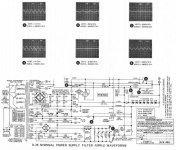
Of course, the other major feature of regulators is their ability to regulate against line side voltage variations and noise. The simulations I’m using will account for nearly everything on the line side except for the transformer. This should be close enough. Here is the basic circuit that I’ll be using:
I’m using a 5AR4 rectifier model. It is very hard to account for the fact that the rectifier is actually rectifying AC while doing this analysis. In fact, I don’t know how to do it. So, I’m simply applying a DC voltage to the plates to make them conduct as though they were seeing half cycles. I don’t think that this is a serious limitation, but I welcome comments here please.
The B+ is supplied with a 10VAC source and the load is a constant current sink. The AC source represents signals on the line other than the main. We are going to sweep the frequency of this signal. The constant current sink eliminates load effects and enables us to do some calculations quickly. What we want to know for each of our regulators is how much of the AC gets into the load, that is, how much shows up as delta-V.
I’m going to show two graphs for each simulation. The first one is simply the ratio of delta-V/delta-B (where delta-B is always 10). Call this F (for Fraction of voltage at the output). So:
F = delta-V / delta-B
The second one is a little trickier. What we want is a measure of the resistive impedance of the regulator. But, this has to be measured by the drop across the regulator. We know that:
350V – V = I * R (at idle)
where R is the resistance of the regulator. Now, if we add delta-B to the source voltage we will get a delta-V. And if the regulator is “regulating” then we’ll also get a delta-R. We can write:
350V + delta-B – V – delta-V = I * (R + delta-R)
and solving this for delta-R we get (using the first equation to cancel out some terms because I is constant):
delta-R = (delta-B – delta-V) / I
This is a measure of how good the regulator is, how much it resists the changes on the line side. The perfect regulator will have delta-V=0. Setting delta-V=0 gives a perfect regulation delta-R=delta-B/I. Since I=10mA, perfect delta-R=1K. Anything smaller than this means that the regulator is not 100% compensating for changes in the source voltage.
Analysis posts to follow.
Yes. Some good discussion about caps that we can analyze later. Back to regulators.
Of course, the other major feature of regulators is their ability to regulate against line side voltage variations and noise. The simulations I’m using will account for nearly everything on the line side except for the transformer. This should be close enough. Here is the basic circuit that I’ll be using:
An externally hosted image should be here but it was not working when we last tested it.
I’m using a 5AR4 rectifier model. It is very hard to account for the fact that the rectifier is actually rectifying AC while doing this analysis. In fact, I don’t know how to do it. So, I’m simply applying a DC voltage to the plates to make them conduct as though they were seeing half cycles. I don’t think that this is a serious limitation, but I welcome comments here please.
The B+ is supplied with a 10VAC source and the load is a constant current sink. The AC source represents signals on the line other than the main. We are going to sweep the frequency of this signal. The constant current sink eliminates load effects and enables us to do some calculations quickly. What we want to know for each of our regulators is how much of the AC gets into the load, that is, how much shows up as delta-V.
I’m going to show two graphs for each simulation. The first one is simply the ratio of delta-V/delta-B (where delta-B is always 10). Call this F (for Fraction of voltage at the output). So:
F = delta-V / delta-B
The second one is a little trickier. What we want is a measure of the resistive impedance of the regulator. But, this has to be measured by the drop across the regulator. We know that:
350V – V = I * R (at idle)
where R is the resistance of the regulator. Now, if we add delta-B to the source voltage we will get a delta-V. And if the regulator is “regulating” then we’ll also get a delta-R. We can write:
350V + delta-B – V – delta-V = I * (R + delta-R)
and solving this for delta-R we get (using the first equation to cancel out some terms because I is constant):
delta-R = (delta-B – delta-V) / I
This is a measure of how good the regulator is, how much it resists the changes on the line side. The perfect regulator will have delta-V=0. Setting delta-V=0 gives a perfect regulation delta-R=delta-B/I. Since I=10mA, perfect delta-R=1K. Anything smaller than this means that the regulator is not 100% compensating for changes in the source voltage.
Analysis posts to follow.
The first regulator is just a wire. This means that we'll be testing the two stage RC filter that is already there. We will do this for C=10u and C=330u to see the differences. There will be no surprises here, but it will establish a baseline for the active regulators.
Here is the graph of F for C10u
What this says is that at 10Hz about 80% of line variations will get through to the load. At 100Hz, less than 10% will. Decreasing from there.
Here is the delta-R plot.
What this says is that at 10Hz the regulator resistance to line variations is about 250ohms. Much less than the perfect 1K. At 100Hz the resistance is about 900ohms. Etc.
Now, for C=330u things will obviously get better. How much?
Here is F:
You get the idea from above. At 10Hz the delta-V is less than 1% of line signals. Here is the delta-R:
The worst delta-R is 990ohms. Much better than before.
So, big caps do work, even if they do suck.
Here is the graph of F for C10u
An externally hosted image should be here but it was not working when we last tested it.
What this says is that at 10Hz about 80% of line variations will get through to the load. At 100Hz, less than 10% will. Decreasing from there.
Here is the delta-R plot.
An externally hosted image should be here but it was not working when we last tested it.
What this says is that at 10Hz the regulator resistance to line variations is about 250ohms. Much less than the perfect 1K. At 100Hz the resistance is about 900ohms. Etc.
Now, for C=330u things will obviously get better. How much?
Here is F:
An externally hosted image should be here but it was not working when we last tested it.
You get the idea from above. At 10Hz the delta-V is less than 1% of line signals. Here is the delta-R:
An externally hosted image should be here but it was not working when we last tested it.
The worst delta-R is 990ohms. Much better than before.
So, big caps do work, even if they do suck.
Series Regulator
We’ll use the series regulator from before. In this case, the cap across the output is 470n. No big electrolytics used. Here it is again (substitute this in for the regulator box above).
First, we’ll test this regulator for C=10u. Here is F:
This says that at 10Hz only 14% of the line noise will get through. Compare this to the pure RC PS at C=10u. In fact, this number is almost as good as the RC PS with C=330u.
Here is the delta-R:
No surprise, just about as good as the RC PS with C=330u.
Can we do better? Well, how about C=330u? Here is F:
At 10Hz only about 0.016% of the line noise will get through to the load (and this is without a large cap on the load side of the regulator). Decreasing with frequency.
For delta-R we have:
Amazingly the delta-R only deviates from perfect delta-R by about 2ohms at its worst. Pretty good resistance to line side ac signals.
Based on this analysis, recognizing that the simulation components are perfect and real components are not, it would appear the one could get away with this series regulator without a load cap as long as you provide the stabilizing cap. In which case, you don’t have to put a nasty electrolytic on the B+ side of your circuit.
I sure would like comments here about how realistic this is in practice.
We’ll use the series regulator from before. In this case, the cap across the output is 470n. No big electrolytics used. Here it is again (substitute this in for the regulator box above).
An externally hosted image should be here but it was not working when we last tested it.
First, we’ll test this regulator for C=10u. Here is F:
An externally hosted image should be here but it was not working when we last tested it.
This says that at 10Hz only 14% of the line noise will get through. Compare this to the pure RC PS at C=10u. In fact, this number is almost as good as the RC PS with C=330u.
Here is the delta-R:
An externally hosted image should be here but it was not working when we last tested it.
No surprise, just about as good as the RC PS with C=330u.
Can we do better? Well, how about C=330u? Here is F:
An externally hosted image should be here but it was not working when we last tested it.
At 10Hz only about 0.016% of the line noise will get through to the load (and this is without a large cap on the load side of the regulator). Decreasing with frequency.
For delta-R we have:
An externally hosted image should be here but it was not working when we last tested it.
Amazingly the delta-R only deviates from perfect delta-R by about 2ohms at its worst. Pretty good resistance to line side ac signals.
Based on this analysis, recognizing that the simulation components are perfect and real components are not, it would appear the one could get away with this series regulator without a load cap as long as you provide the stabilizing cap. In which case, you don’t have to put a nasty electrolytic on the B+ side of your circuit.
I sure would like comments here about how realistic this is in practice.
Shunt Regulator
Here is our trusty old 6DJ8 shunt regulator. The tube is actually working above its maximum voltages, but the model works perfectly all right there. Here is the diagram:
Running the same analyses, setting C=10u first, we get for F:
By now you know the drill. This regulator is not bad at line variations, but not especially good. Here is the delta-R:
delta-R drops by about 90ohms max. Not bad, but not great.
For C=330u, we get for F:
F drops by about a factor of 10 to 0.8% noise getting through at 10Hz. And R:
R drops by 8ohms at 10Hz. Compared to 2ohms for the series regulator.
This is not a bad regulator. Unfortunately, in this analysis the regulator is bypassed with a capacitor. I should try this again with an additional series resistor (the way this is supposed to work). Maybe later, but my hunch is that it would be almost as good as the series regulator.
I'm pretty worn out now. I'll post the SS regulator results tomorrow. Once again, I welcome comments.
Here is our trusty old 6DJ8 shunt regulator. The tube is actually working above its maximum voltages, but the model works perfectly all right there. Here is the diagram:
An externally hosted image should be here but it was not working when we last tested it.
Running the same analyses, setting C=10u first, we get for F:
An externally hosted image should be here but it was not working when we last tested it.
By now you know the drill. This regulator is not bad at line variations, but not especially good. Here is the delta-R:
An externally hosted image should be here but it was not working when we last tested it.
delta-R drops by about 90ohms max. Not bad, but not great.
For C=330u, we get for F:
An externally hosted image should be here but it was not working when we last tested it.
F drops by about a factor of 10 to 0.8% noise getting through at 10Hz. And R:
An externally hosted image should be here but it was not working when we last tested it.
R drops by 8ohms at 10Hz. Compared to 2ohms for the series regulator.
This is not a bad regulator. Unfortunately, in this analysis the regulator is bypassed with a capacitor. I should try this again with an additional series resistor (the way this is supposed to work). Maybe later, but my hunch is that it would be almost as good as the series regulator.
I'm pretty worn out now. I'll post the SS regulator results tomorrow. Once again, I welcome comments.
dBs are wonderful things
When analysing this sort of thing, it's much easier to compare design approaches if the graph's vertical scale is in dBs of rejection.
The other thought is that although rectified AC has a DC component, and you don't theoretically need a reservoir capacitor, the AC component is quite large, and a practical regulator would need to drop a lot of volts to avoid dropout.
OK. A physicist's work is never done.
Unfortunately, I can't put all of these on one graph and then label them, which would show the comparison best. So here are the six previous Fs in DB of rejection.
RC filters only, C=10u
RC filters only, C=330u
Series regulator, C=10u
Series regulator, C=330u
Shunt regulator, C=10u
Shunt regulator, C=330u
Hope this helps some.
Yes. It's becoming clear to me that, if big electrolytics are really bad news, it is possible to minimize their use and their size by careful cascading of regulators.
Unfortunately, I can't put all of these on one graph and then label them, which would show the comparison best. So here are the six previous Fs in DB of rejection.
RC filters only, C=10u
An externally hosted image should be here but it was not working when we last tested it.
RC filters only, C=330u
An externally hosted image should be here but it was not working when we last tested it.
Series regulator, C=10u
An externally hosted image should be here but it was not working when we last tested it.
Series regulator, C=330u
An externally hosted image should be here but it was not working when we last tested it.
Shunt regulator, C=10u
An externally hosted image should be here but it was not working when we last tested it.
Shunt regulator, C=330u
An externally hosted image should be here but it was not working when we last tested it.
Hope this helps some.
The other thought is that although rectified AC has a DC component, and you don't theoretically need a reservoir capacitor, the AC component is quite large, and a practical regulator would need to drop a lot of volts to avoid dropout.
Yes. It's becoming clear to me that, if big electrolytics are really bad news, it is possible to minimize their use and their size by careful cascading of regulators.

Solid State Series Regulator
As promised, here is the final installment for line regulation. Here is the SS series pass regulator that we used before. Plug this into the PS design shown previously:
For the small cap, C=10u, here is the PS rejection figure in DB for line noise:
And here is the delta-R:
Both of these graphs show that the SS regulator beats all of the other regulators. Furthermore, when we increase C to 330u we get a rejection factor like this:
And a delta-R like this:
This regulator is approaching perfection.
And so, the real champion in all of this, assuming that the simulations bear some resemblance to reality is our inexpensive, low part count BJT regulator.
As promised, here is the final installment for line regulation. Here is the SS series pass regulator that we used before. Plug this into the PS design shown previously:
An externally hosted image should be here but it was not working when we last tested it.
For the small cap, C=10u, here is the PS rejection figure in DB for line noise:
An externally hosted image should be here but it was not working when we last tested it.
And here is the delta-R:
An externally hosted image should be here but it was not working when we last tested it.
Both of these graphs show that the SS regulator beats all of the other regulators. Furthermore, when we increase C to 330u we get a rejection factor like this:
An externally hosted image should be here but it was not working when we last tested it.
And a delta-R like this:
An externally hosted image should be here but it was not working when we last tested it.
This regulator is approaching perfection.
And so, the real champion in all of this, assuming that the simulations bear some resemblance to reality is our inexpensive, low part count BJT regulator.
runeight said:Solid State Series RegulatorAnd so, the real champion in all of this, assuming that the simulations bear some resemblance to reality is our inexpensive, low part count BJT regulator.
Yes, a simple regulator can be surprisingly good, but achieving practical rejection better than 90dB is almost impossible, which suggests that the models aren't as complete as one would like.
One problem is wiring resistances and earth points. It doesn't take much resistance in a 0V circuit to degrade attenuation.
Was the 200V Zener a full model? High voltage "Zeners" (actually avalanche) tend to have quite high slope resistance.
I'd like to make it quite clear I'm not belittling your efforts. If a model could be made that produced realistic results, playing with it would be enormously valuable.
Did you include shunt capacitance between end caps of the 22k resistor (probably about 0.5pF)? Very few plastic capacitors achieve ESR < 1R!
Hi,
On paper? Perhaps...
I feel its way too early in this study to jump to conclusions.
Theoretical performance is one thing, sonic performance is quite another.
More work for the physicist, he?
Thanks for all the hard work done so far anyway,
This regulator is approaching perfection.
On paper? Perhaps...
I feel its way too early in this study to jump to conclusions.
Theoretical performance is one thing, sonic performance is quite another.
More work for the physicist, he?
Thanks for all the hard work done so far anyway,
There are many limitations in the models, including the basic Rs and Cs. The zener is one of the standard zener models included with the simulator. These are pretty sophisticated, but they are far from perfect. THe zener was biased about 2mA (I think).
You guys are, of course, correct on all counts. EC, I know you're not belittling the work at all, just pointing out the practical reality of real components connected with real wires inside of a real chassis exposed to real radiation, etc. The world is a very non-linear place. But hey, -400db was looking pretty good.
Way too early? It's already been six pages, 1000 plots and drawings, and 10000 simulations!
In truth, I have think about where to go from here. Mostly I was trying to see if the regulators actually affected the audio circuit and how. I do think that the simulations can give good relative indications and in this case, some regulators are better than others, but not in non-obvious ways.
So, help me make the deeper connection between what the regulators are doing and the audio beyond what we've looked at here and I'll follow (and even do some more work).
You guys are, of course, correct on all counts. EC, I know you're not belittling the work at all, just pointing out the practical reality of real components connected with real wires inside of a real chassis exposed to real radiation, etc. The world is a very non-linear place. But hey, -400db was looking pretty good.
I feel its way too early in this study to jump to conclusions.
Way too early? It's already been six pages, 1000 plots and drawings, and 10000 simulations!
In truth, I have think about where to go from here. Mostly I was trying to see if the regulators actually affected the audio circuit and how. I do think that the simulations can give good relative indications and in this case, some regulators are better than others, but not in non-obvious ways.
So, help me make the deeper connection between what the regulators are doing and the audio beyond what we've looked at here and I'll follow (and even do some more work).
- Status
- This old topic is closed. If you want to reopen this topic, contact a moderator using the "Report Post" button.
- Home
- Amplifiers
- Tubes / Valves
- Regulated Supplies in Tube Amps