I just built a lampizator output (similar to tubizator) as I had the parts lying around but never got around to building it. Comparing to the Pedja Rogic stage, my first impressions are:
- Tubes are more 'sweet' than the DDNF stage.. a bit more highs
- Indeed the DDNF stage is more punchy
- The bass of the tubes is quite boomy to my taste, there is not much detail in the bass
- The DDNF stage has more definition (must admit that my DDNF stage is powered with Salas shunts, and the tube stage with a linear psu)
I quite understand why you would like to switch between them, as both have their hightlights. Some music just sounds better with one stage than the other.
I just built a lampizator output (similar to tubizator) Some music just sounds better with one stage than the other.
What tubes are you using? I find sub stantial difference between 6n2p and 6n1p for example.
I'm on 6n2p now
Nice choice. Of course the coupling caps are a key part. I am running Obligato PIO 2u. Work well. Russian KBG are a step up. I bypassed them with .1u Russian Tefon, and the HF opened up a new window. Very cost effective.
I suspect the quality of R1 and R2 are equally important, but I have yet to test. I did add a cathod bypass cap to R1, and like the effect. just put a 150u 16v Oscon SEP on the resistor. It added more grunt and texture to the lower end.
B+ power quality counts but not as much as cap choice. adding good transformer and a choke cleared away a little haze.
I am using
B+ = 190v
Rk= 200ohm kiwame
Riv= 50 ohm shinkoh
Output caps = obbligato gold 2.2uf
Should be fine, and it sounds fine.
Almost identical to my setup. I have Riv at 90 ohms. Lampizator claims its a bit more laid back at 50. I have not experimented so no idea.
Hi Oliver,
I fired up my DAC for the first time last night, and everything seemed to work fairly well. I'm using a CD player with digital out as a transport. I'm using the Twisted Pear SPDIF converter through your high speed buffer.
Today I turned it on, and I'm getting music out of the the left channel only.
When I turned up the regulator supplying them to 5.5v I got sound out of both channels but it was very distorted.
Any ideas?
Ned
I can advise you here neda, as I have also faced this issue.
This is related to the use of two sets of shunt regulators. The Salas shunts are more than capable of supplying excellent, consistent and ripple-free supply to the DAC, but the TL431 shunt regulators that are in the way make things less simple.
Essentially, you have two options.
Option one, which is by far the simplest, and something you should try until you get a chance to operate and go with Option two, is to turn the Vout of the Salas shunts up to around 7vDC -7vDC -17vDC, which will supply the TL431s with sufficient voltage that they have some work to do. This should solve your immediate problems (but do check their output voltages are around 5v -5v & -15v).
Option two, is something that I was the first to do with this project. Remove the TL431s and all associated Cs & Rs. It is all discussed in great depth in this thread, and Oliver gave some great advice on where to "inject" the Salas shunts after removing the TL431s. The improvement is considerable. Several people have tried this, and all have so far recorded improvements. Oliver's latest V3.0 DAC board is basically a neater version of the de-TL431-ed board, with some refinements, I believe.
Last edited:
Hi Oliver,
I fired up my DAC for the first time last night, and everything seemed to work fairly well. I'm using a CD player with digital out as a transport. I'm using the Twisted Pear SPDIF converter through your high speed buffer.
Today I turned it on, and I'm getting music out of the the left channel only.
When I turned up the regulator supplying them to 5.5v I got sound out of both channels but it was very distorted.
Any ideas?
Ned
Hi Ned,
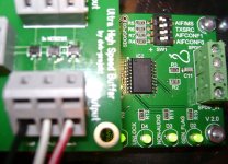
please post some pictures of your setup. I would like to look especially to the DIP-Switches on the TP SPDIF converter.

I can advise you here neda, as I have also faced this issue.
This is related to the use of two sets of shunt regulators. The Salas shunts are more than capable of supplying excellent, consistent and ripple-free supply to the DAC, but the TL431 shunt regulators that are in the way make things less simple.
Essentially, you have two options. The first option, which is by far the simplest, and something you should try until you get a chance to operate and go with the second option, is to turn the Vout of the Salas shunts up to around 7vDC -7vDC -17vDC, which will supply the TL431s with sufficient voltage that they have some work to do. This should solve your immediate problems (but do check their output voltages are around 5v -5v & -15v).
Option two, is something I was the first to do with this project, and many others have now, like me, recorded improvements with. Namely, remove the TL431s and all associated Cs & Rs. It is all discussed in great depth in this thread, and Oliver gave some great advice on where to "inject" the Salas shunts after removing the TL431s. The improvement is considerable. Oliver's latest V3.0 DAC board is basically a neater version of the de-TL431-ed board, with some refinements, I believe.

Nice choice. Of course the coupling caps are a key part. I am running Obligato PIO 2u. Work well. Russian KBG are a step up. I bypassed them with .1u Russian Tefon, and the HF opened up a new window. Very cost effective.
I suspect the quality of R1 and R2 are equally important, but I have yet to test. I did add a cathod bypass cap to R1, and like the effect. just put a 150u 16v Oscon SEP on the resistor. It added more grunt and texture to the lower end.
B+ power quality counts but not as much as cap choice. adding good transformer and a choke cleared away a little haze.
Lukas "Lampizator" Fikus has also staked his reputation on the fact that, when he set up an immediate A, B test to determine differences between output DC blocking, or "coupling" caps, he couldn't determine any single difference between any of them, including cheap electrolytic ones.
Go figure!
captest1
It certainly is an interesting read, and perhaps suggests what many have suspected all along - that the cost and effort of upgrading certain parts, along with the excitement of doing so, coupled with the time lag it takes to perform an operation on our gear, creates a powerful psycho-acoustic effect.
 Only live A, B switching can determine the best part, I feel.
Hi Ned,
please post some pictures of your setup. I would like to look especially to the DIP-Switches on the TP SPDIF converter.
Hi Oliver,
When I touch the meter probe to the BCK terminal of the buffer board I get distorted sound from both channels. Remove the probe, and I get clear sound from left channel only.
Attachments
[
Hi Lucas,
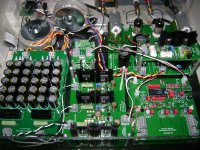
As you can see from the photo, I'm using option two.
The second +5v line is bridged from underneath the board.
Ned
I can advise you here neda, as I have also faced this issue.
This is related to the use of two sets of shunt regulators. The Salas shunts are more than capable of supplying excellent, consistent and ripple-free supply to the DAC, but the TL431 shunt regulators that are in the way make things less simple.
Essentially, you have two options.
Option one, which is by far the simplest, and something you should try until you get a chance to operate and go with Option two, is to turn the Vout of the Salas shunts up to around 7vDC -7vDC -17vDC, which will supply the TL431s with sufficient voltage that they have some work to do. This should solve your immediate problems (but do check their output voltages are around 5v -5v & -15v).
Option two, is something that I was the first to do with this project. Remove the TL431s and all associated Cs & Rs. It is all discussed in great depth in this thread, and Oliver gave some great advice on where to "inject" the Salas shunts after removing the TL431s. The improvement is considerable. Several people have tried this, and all have so far recorded improvements. Oliver's latest V3.0 DAC board is basically a neater version of the de-TL431-ed board, with some refinements, I believe.
Hi Lucas,
As you can see from the photo, I'm using option two.
The second +5v line is bridged from underneath the board.
Ned
Attachments
Hi Ned,
please post some pictures of your setup. I would like to look especially to the DIP-Switches on the TP SPDIF converter.
Hi Oliver,
When I touch the meter probe to the BCK terminal of the buffer board I get distorted sound from both channels. Remove the probe, and I get clear sound from left channel only.
Hi Ned,
looks real great!
The settings on the TP are correct. Two questions:
1. Did you power up the whole DAC with an SPDIF input signal or without anything?
2. Did you try to disconnect one of the DAC modules?
Hi Ned,
looks real great!
The settings on the TP are correct. Two questions:
1. Did you power up the whole DAC with an SPDIF input signal or without anything?
2. Did you try to disconnect one of the DAC modules?
Hi Oliver,
First I powered it up without the transport, and set all voltages then powered down. Next I connected it to the transport, powered it up, and everything worked fine.
The next day, like a fool, I decided to play with the dip switch settings to see if it had any effect on the sound, cycling on & off between switch changes. That's when my troubles began.
Could I have possibly burnt something out by cycling to quickly?
No, I did not try to disconnect one of the DAC modules. Should I?
Ned

Thank you Oliver & Lucas for your help, I found the problem!
It was what we learned on our first day of electronics 101.
Make sure your GROUNDS are tight!!!
The input gnd to the converter was loose.
We're back in buisness, and sounding good, but still have a long way to go.
Best Regards,
Ned
It was what we learned on our first day of electronics 101.
Make sure your GROUNDS are tight!!!
The input gnd to the converter was loose.
We're back in buisness, and sounding good, but still have a long way to go.
Best Regards,
Ned
- Status
- This old topic is closed. If you want to reopen this topic, contact a moderator using the "Report Post" button.
- Home
- Group Buys
- "Reference" TDA1541A DAC with I2S-BUS architecture