Thanks POS for all the hints, they are very helpful for getting a handle on the process. Still just stumbling around with what can be done but it's a start.
Add: I keep reading back over POS' post and finding more information that I didn't pick up on the first pass. It's going to take me a while to digest everything I think.
I'm basically just having a play around at the moment - as I'm not sure what does what
I've attached a .skr with the 44.1 filter replaced with a minimum phase filter, linkwitz riley "shape" and 12dB filter slope and corner frequency of 159994.8Hz. My numbers are probably off but I'm setting the corner frequency at 0.4535*fs where the fs is 44100 * 8. (I re-read POS's post and corrected from 384 -> 352.8, oops)
I'm not sure why, but the rePhase filter is about 6dB quieter than the one Søren made, so
******* Beware, Warning, Actung, Alert, Danger *******
The 44.1khz filter is significantly quieter than the official filters. If you change to a higher sampling rate without adjusting volume it will be significantly louder. Be warned!!
*************
Anyway don't expect perfection, because I'm no expert in filter design, but might be of interest to someone!
And a question... is there a way to visualise impulse response in rePhase?
cheers
Paul
Hi Paul,
You are welcome
")
I don't see why the filter would be 6dB lower than the original one.
I loaded the original 44.1kHz filter and it had a 0dB passband, exactly like the one I generated with rephase.
Did you compare 44.1 vs 96, or 44.1 vs 48 ?
Can you share your rephase file (if you saved it) as well as the txt file that you send to the DAC (the one with all the FIR filters).
As to how to visualize the impulse, I am afraid you cannot do that within rephase
You can load the txt impulse into REW or Holm though, and see both the impulse and the amplitude response (this one should be identical to the one showed in rephase).
You can also save the impulse as a wav file and load it into audacity.
Finally you can even copy/paste the coefficients from the txt file into an excel or google doc spreadsheet...
Here is an example:
https://docs.google.com/spreadsheets/d/1sD6tDVs1dOZBtvq55MwtweORHyZERlTpqLgS_ZHFL9o/edit?usp=sharing
I will try to implement a few filter proposal and post them on the forum, with graphical response and impulse curves...
Yes, at least that is the planpos - cant you take a stab at a 44,1 filer - please?
I have no experience in designing/comparing reconstruction filters, but these are simple LP filters so I have got the tools to build them.
I will try to emulate the "filter 1" and "filter 2" settings from this DAC:
Arcam FMJ D33 D/A processor Follow-Up, April 2013 | Stereophile.com
(the default filter being similar to the one currently implemented in Soren's DAC)
Here is what John Atkinson had to say about these filters (in the comments lower down the page).
John Atkinson said:Robby said:Would you pick the Arcam as a DAC for yourself if you were shopping for a DAC in that price range?
Yes, because its F1 filter is one of the best-sounding reconstruction filters I have tried.
John Atkinson
Editor, Stereophile
Last edited:
TCR
What are TCR values for 0.05%, 0.02% and 0.01% resistors used?
When testing we do a FFT and measure distortion at -1db, we don't really see any difference between the different version as the initial precision is so good, even on less precise resistors.
But I expect long term the boards with more precise resistors will change less than the less precise resistors as temperature and long term drift are significant better with the more precise resistors....
What are TCR values for 0.05%, 0.02% and 0.01% resistors used?
The sequences and intermediate sample rates and fixed in hardware.
As the hardware is a FPGA there is some hope this is not cast in stone (resp. silicone)
Hi Soren,
You can either combine several filters, minimum-phase and linear-phase, possibly at different frequencies (spread the poles), or you can generate a linear-phase filter and then partially linearize its phase with the "phase linearization" tab.
I will try to post e few examples tonight.
As for the saturation, I was not worried about the coefficients themselves, but the result of the convolution: even it the resulting amplitude curve does not exceed 0dB you can still get saturation because of the phase shifts.
Would be great with some filter example, I don't really understand rePhase's settings, it's kinda the first time I do digital filters....
And I'm still not worried about saturation, have plenty of guard bits in the different stages, all the way to the final volume control stage....
What are TCR values for 0.05%, 0.02% and 0.01% resistors used?
I think it's in one of the early post in this thread, but anyway, the resistors I use are:
0.01% / 5 ppm/C
0.02% / 10 ppm/C
0.05% / 25 ppm/C
Hi Paul,
You are welcome
I don't see why the filter would be 6dB lower than the original one.
I loaded the original 44.1kHz filter and it had a 0dB passband, exactly like the one I generated with rephase.
Did you compare 44.1 vs 96, or 44.1 vs 48 ?
Can you share your rephase file (if you saved it) as well as the txt file that you send to the DAC (the one with all the FIR filters).
As to how to visualize the impulse, I am afraid you cannot do that within rephase
You can load the txt impulse into REW or Holm though, and see both the impulse and the amplitude response (this one should be identical to the one showed in rephase).
You can also save the impulse as a wav file and load it into audacity.
Finally you can even copy/paste the coefficients from the txt file into an excel or google doc spreadsheet...
Here is an example:
https://docs.google.com/spreadsheets/d/1sD6tDVs1dOZBtvq55MwtweORHyZERlTpqLgS_ZHFL9o/edit?usp=sharing
I will try to implement a few filter proposal and post them on the forum, with graphical response and impulse curves...
Thanks again POS.
I think it was user error. I had the corner frequency set at 0.4535 * fs * 8 so it wasn't doing anything useful. I've corrected this to 0.4535 * fs and it looks more sensible, but I haven't tested these as yet.
As a work around for visualisation I'm exporting as a 32bit mono .wav and loading into Izotope RX4.
I haven't loaded these yet so untested but I have attached a zip with:
- .rephase project for a minimum-phase filter
- 1021filt_MP.txt text file with minimum-phase fir parameters pasted into it.
- processed LP and MP filters for 44.1 as .skr files
- screen shots of rePhase configurations used
- screen shots of impulse overlaid on spectrogram in RX4
cheers
Paul
Attachments
Paul, nice result!
(no need to use "maximal" optimization here: it seems to do nothing useful in your situation: it simply tries many step before giving up...)
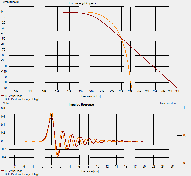
Here is an alternative version, as an example, with an additional steep linear-phase filter up high. The signal is already attenuated by the minimum-phase filter when it reaches that point, so the pre ringing is minimal.
(copy/paste it in a ".rephase" file (there will be a "load from clipboard" function in the next version))
The response curve is similar to Soren's filter, but mostly minimum-phase.
It should be quite close to the "filter1" setting from the stereophile article I posted above, so hopefully it will sound good
Attached is the response curve and impulse of that filter in orange, and yours in red.
The impulse response is close to your filter, but with less post ringing and some traces of pre ringing.
(no need to use "maximal" optimization here: it seems to do nothing useful in your situation: it simply tries many step before giving up...)
Here is an alternative version, as an example, with an additional steep linear-phase filter up high. The signal is already attenuated by the minimum-phase filter when it reaches that point, so the pre ringing is minimal.
(copy/paste it in a ".rephase" file (there will be a "load from clipboard" function in the next version
))
Code:
rePhase settings
eNrtm82OmzAQx18l8qmVsggMJJBj1Qdoe11FyAET3AKmYJL90L57x3ZgSWCrHvbQViOtsvHMeMb+
/c2uxMjP5CAfklyUircd2d3fE7Imfkj264Vv+zVJeQ2Roj6SHalElpUcfGnB0x9dX4EtDg809jKa
5izY+iyiWZwHmbelccDSLM10dCu77rak57ruUOp9v8Ois0NSsQdYnecSOxI1jO680Iz5cXBH4/gS
YAywVF6zioNFVE1fdtwY26s9lPJ817CuA9c3/p2nalWIYwEj6gb60zG1XGfrbvWQDuvUUcNE+Ami
ebCHsZNY0DOXbcUUyOHT1UGobpWXksGvStZy9cFRD+ojGaKSEygkpJbTc1wK9iMz4rqOzn3kP0G+
Z8JSJU6gsLcm9ixswNkUrONJy0umbAY4FqLqqzvjgAD12OhTkcq6U6xWq69gO7Gy5/ZM2BJe6Gxo
aLZjt2rNNHAi15+Z/djxt3Rm3gCLmTGOHerNY71w6wTxvKCBeVtt40ThQrXYiTfzxFqAebUIyi1U
82InmpmDpRQbP4idxXLb+Ta8zVIKGvrxWG3/sp4runkHPSdqUlN7ouNoGBQcDVa7cTioNhoGvV5T
aqUm+axGk3xWndcEhsgkn1Vkks9qMRqC6wkD/2nC7XRBF+aThIY2RdJIGkkjaSSNpJE0kkbSSBpJ
I2kkjaSRNJJG0kgaSf8zpPdrUoiMJxah7n+YN63Fk+2PhDDRtUP9Bj00I/F2H+RTr8B8lq0qzE4g
V92X5aQL4obuxbjQAqDBbbxlg+G/DQcRK866vuUVrxXZPZPDo5m6A7UyphjIZCaPH3vbE0lknndc
t1WM6NODoA2iPvF28MIjpXpIqVejRMWnc1/WpJaKW6dswC2erh5SVt44kryUsjUHjurszVtNmdhd
6soMj/id6ezMn/yulA3Hzsxf25mJ3XcSFf+k/8k/T8SNuBE34kbciBtxI27EjbgRN+JG3IgbcSNu
xI24Eff/3ORpZMlaoR6BXi3bSr/PZ1VTTt7imwsVg93e9vFDGpnXu53M1Zm1mn3Lv1y6bYMx6frD
5a7MgvPqLobjfta+/nB7F4iON3iuv8HKFWs6c4/HC4fOQyZanl6OyGU348loL64V7ErBNnT/5Czq
TJ7tngpW65N0blkz9Dq8l1/MGoph
The response curve is similar to Soren's filter, but mostly minimum-phase.
It should be quite close to the "filter1" setting from the stereophile article I posted above, so hopefully it will sound good
Attached is the response curve and impulse of that filter in orange, and yours in red.
The impulse response is close to your filter, but with less post ringing and some traces of pre ringing.
Attachments
For those of us who are battery enthusiasts -
Is it possible to be shown where the +- 4 volts regs are located on the board?
They are very well hidden!
THANKS!
Sorry, this is still a commercial product, there are limits to how deep modifications I can or will support....
I can only recommend to supply any power on J1, and J3 is NOT for supplying power.
If you insist to improve the onboard power supply, try replacing the 6 electrolytic capacitors with aluminum polymer types, 1000u 16V exist in same 10mm smd footprint and t.ex. digikey stock them at $2.20 each. Should be easy to replace.
So much has been said about the CHORD Hugo DAC.
Any way of looking in there to see that they did with their filters?
hugo can be a little shouty too, but def ahead in sq
So much has been said about the CHORD Hugo DAC.
Any way of looking in there to see that they did with their filters?
No company is going to give significant details of the filters. You'll often read the claims that the filters have been developed and optimised with lengthy periods of research, design and listening tests, and they are a point of differentiation in the market place.
The best that we can do is read the tech "white papers" some manufacturers produce, and look at the testing done in Stereophile since early 2013 which gives an indication of the shape of the filter curve and it's impulse response. From there it's a matter of trying to replicate as far as possible - and the odds are still very remote you'd get exactly the same behaviour as the original filter.
Here is an alternative version, as an example, with an additional steep linear-phase filter up high. The signal is already attenuated by the minimum-phase filter when it reaches that point, so the pre ringing is minimal.
....
The response curve is similar to Soren's filter, but mostly minimum-phase.
It should be quite close to the "filter1" setting from the stereophile article I posted above, so hopefully it will sound good
Attached is the response curve and impulse of that filter in orange, and yours in red.
The impulse response is close to your filter, but with less post ringing and some traces of pre ringing.
Now I'm getting the rePhase setting, it's kinda mixing linear phase and minimum phase with those settings.... Sorry if I didn't pay enough attention to you at first.
I will also work to generate a complete set of filters, looking at the impulse and square waves and listening a little....
I don't have time to listen that much, but if everybody listen some and we then can agree on a set of filters, then the R-2R DAC should reach its maximum potential....
You can take 5V from the dam1021, but as the input lines to the dam1021 are 3.3V only you need to divide down the output voltage from the toslink receiver. Looking at the datasheet it have a IOH current of 1 mA, so maybe it's some king of OC already ? Try loading the output down with a 2.2K resistor first....
Voila, I got it sound in the first try your comment! To me the sound now is more music, natural, detail... And there still many way I can improve!
Thanks for nice job Soren!
PS: the DAC some time lose the lock for few second, but I think I could fix around with resistor at SPDIF output
Now I'm getting the rePhase setting, it's kinda mixing linear phase and minimum phase with those settings.... Sorry if I didn't pay enough attention to you at first.
I will also work to generate a complete set of filters, looking at the impulse and square waves and listening a little....
I don't have time to listen that much, but if everybody listen some and we then can agree on a set of filters, then the R-2R DAC should reach its maximum potential....
I will testimonie when the spk will be ready if it changes somethings to me in the soundstage (have like a hole between the speakers but not everyone has one, most haven't), have time to listen and check in the day .
Now I'm getting the rePhase setting, it's kinda mixing linear phase and minimum phase with those settings.... Sorry if I didn't pay enough attention to you at first.
I will also work to generate a complete set of filters, looking at the impulse and square waves and listening a little....
I don't have time to listen that much, but if everybody listen some and we then can agree on a set of filters, then the R-2R DAC should reach its maximum potential....
Søren,
Is it necessary to restart the DAC for the new filter settings to take effect or can we get away with toggling sampling rates or something like that?
cheers
Paul
How to connect the DAC to a commercial USB to Spdif converter (like Brezee audio) what has already an output traffo with its spidf????
Tyimo,
Treat the USB to SPDIF as you would a CD Transport or similar. It is a SPDIF transmitter and it makes no difference if it has a trafo or not. All that matters is that the output jack is driven correctly, and you have to assume the designers have done this correctly. FWIW I'm using a Stello U3 USB -> SPDIF interface.
Soren's circuit is a SPDIF reciever, and is designed to correctly terminate the recieving end of the SPDIF line, and to correctly drive the LVDS inputs on the DAC board. The resistor and cap in the power and gnd filter the +1.2V, and block DC from the GND. The idea is to lift the gnu point of the Transformer output to +1.2V which is the common mode voltage the LVDS logic requires.
Basically you can safely build the circuit Søren provided "as is" and it will work correctly with a USB to SPDIF interface with no changes required.
cheers
Paul
- Home
- Vendor's Bazaar
- Reference DAC Module - Discrete R-2R Sign Magnitude 24 bit 384 KHz