
Helloemails get lost sometime.... Please send another email.
No news from my email
Bestregards
Serge
Hi,
After about one year with DAM1021 controlled by arduino next version is finished.
Same DAM1021 reworked.
The changes
New features in FW:
Look:
After about one year with DAM1021 controlled by arduino next version is finished.
Same DAM1021 reworked.
The changes
- full flittered power supply ow instead simple filtration.
- 5 power output - +/- 9V for DAC is independent from 3 other output voltages: 12, 24 and 5 volts.
- analog VU meters per channel connected to 2V line out of DAC
- New ESP32 controller with WiFi
- motorized analog volume control (alps)
New features in FW:
- HomeKit Hub support with remote volume control, filter, input changes, with on / off remote
- HomeKit internal temperature monitoring
- UART interface
- lcd information monitors and leds.
Look:
Attachments
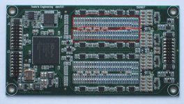
what is the purpose of two ladders in one channel? for SE output?
You can see that its marked in red one channel having two ladders that too for SE output how is this wired? Consider if its balanced output but still the SE output from the last resistor of the ladder.
How does this actually work though. Can anyone explain about it?
You can see that its marked in red one channel having two ladders that too for SE output how is this wired? Consider if its balanced output but still the SE output from the last resistor of the ladder.
How does this actually work though. Can anyone explain about it?
Attachments
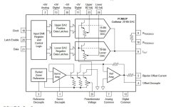
Its mentioned as physically two R-2R strings, one with +4V ref and one with -4V reference (of course very low noise and with very precise tracking), connected together at the output which can be done as a R-2R network has constant output impedance.Linearity:
As I stated, first measurement was even better than expected, didn't really know upfront what the result would be, but remember that THD is RMS measurements.
A regular DAC feed by the two’s complement code has the problem that zero crossing goes from all zero'es to all ones's, meaning the distortion goes up at lower levels. The sign magnitude DAC architecture basically is two DAC's, one for the positive signal and one for the negative signal, resulting in constant distortion at all levels. T.ex. with a -60 db signal, the 10 most significant bits stays at GND for both the negative and positive DAC sections, not the constant switching of all bits....
It's not something I invented, Burr Brown did it with their Colinear chips, starting with the PCM63.... And my DAC is actually physically two R-2R strings, one with +4V ref and one with -4V reference (of course very low noise and with very precise tracking), connected together at the output which can be done as a R-2R network has constant output impedance.
I also use LVC595 chips as drivers, those have about 13R output impedance at 4V, both positive and negative output fets (I measured some sample parts). I have R as 4K99, 2R is then 10K0 with 3.01M parallel to adjust for driver impedance.
Is that what you were mentioning? Well in that case one R2R network is running with +4V and another at -4V
So what is the output waveform of each Network as they seem connected together at the output. Is it just a parallel connection? I dont think they will be out of phase but if they are in phase isnt the distortion sums up?
Attachments
what is the purpose of two ladders in one channel? for SE output?
Because it's a sign magnitude R2R DAC, one ladder for the positive and another for the negative,
by using such two ladders the distortion becomes relative to the actual signal and not to the full signal as with one ladder.
http://www.soekris.dk/tech_info.html
- Home
- Vendor's Bazaar
- Reference DAC Module - Discrete R-2R Sign Magnitude 24 bit 384 KHz