I killed it by being tired and doing the (just this last tweak for today). And by connecting ground of the battery to the circuit and then touching with the plus 3.3v wire the metal case of the clock. Just a small spark and then.... silence. For a long time
As we are at it, are these caps ok? :
10 pcs. A750 KEMET Polymer Kondensator 1500uF 6,3V 14mR 8x12mm RM3,5 #BP | eBay
As we are at it, are these caps ok? :
10 pcs. A750 KEMET Polymer Kondensator 1500uF 6,3V 14mR 8x12mm RM3,5 #BP | eBay
Yes, probably firmware is stopping us. But honestly, I dont think it is a big difference between 514 and 570, there are more important tweaks as mentioned before.
Yes, that's why I am reluctant to go the battery route completely, too small everything. But I will try it for the clock though, letting the battery act as a huge cap being charged constantly by the inboard regulator. I did this with the USB board with very good results.
Might be the traces on the board that's "limiting" the jitter performance we can get. If you're confident performing the mod it's probably okay
The funny part is my original dam1021 that I did the 16 cap mod to sounded similar to what I hear now, I felt I lost something since going dual-mono and adding less capacitance to vref on the basis that it wasn't really needed, but it certainly is all back now! Running roughly 3200uF per rail now factoring in the ceramics. More caps you can tie closer to the shift registers are likely better than a few single larger ones. The smd caps I used specifically digikey part# 732-6399-1-ND
Hearing The Old Ways by Loreena McKennitt just has me grinning once again. Impressed.
Congrats on the success! It does make sense. Longer trace = more ESR ESL probably. And even large electrolytic caps don't have the ESR that multiple paralleled small polymers do, though the shift register internal resistance limits what we can get out of low ESR according to Soren. Also interesting that adding 1300uf improved things when there's already 1500+uF each rail. How much capacitance did the caps have in the 16 cap mod?
I killed it by being tired and doing the (just this last tweak for today). And by connecting ground of the battery to the circuit and then touching with the plus 3.3v wire the metal case of the clock. Just a small spark and then.... silence. For a long time
As we are at it, are these caps ok? :
10 pcs. A750 KEMET Polymer Kondensator 1500uF 6,3V 14mR 8x12mm RM3,5 #BP | eBay
Looks fine to me. You can potentially get to <10mR or >1500uF with Nichicon/FPCAP but if they're harder/more expensive to get then don't worry about it. Do make sure that the leads are 0.6mm if you're using it for dam1021, not sure what is best for 1121 maybe 0.8mm is okay too.
Might be the traces on the board that's "limiting" the jitter performance we can get. If you're confident performing the mod it's probably okay
Congrats on the success! It does make sense. Longer trace = more ESR ESL probably. And even large electrolytic caps don't have the ESR that multiple paralleled small polymers do, though the shift register internal resistance limits what we can get out of low ESR according to Soren. Also interesting that adding 1300uf improved things when there's already 1500+uF each rail. How much capacitance did the caps have in the 16 cap mod?
The original 16 cap mod was 4x 680uF per rail with those surplus Sanyo purple things, can't remember exactly. It was roughly double the 1400 I had and connected to those same pins. ESR likely plays a big role in this as you said with the parallel caps, maybe go for a larger ripple current rating also.
Just impressive, I am glad we all took a 2nd look at this. Cheers
All part of DIY!

The original 16 cap mod was 4x 680uF per rail with those surplus Sanyo purple things, can't remember exactly. It was roughly double the 1400 I had and connected to those same pins. ESR likely plays a big role in this as you said with the parallel caps, maybe go for a larger ripple current rating also.
It's probably nice that you have different kinds of caps paralleled and in very good locations. But we probably need actual simulations to tell for sure how much difference each specification makes, if the change in sound can indeed be reflected in available measurements. For me, there is something really unappealing in pushing my ears to hear subtle differences and trying to make strong statements with it. However, the change this time due to vref was simply impossible to ignore. If my standard of naturalness/musicality is, as I believe, more or less true to the sound of musical performances, then this mod really takes the DAC to a different level.
Hope my reports can be of use to others deciding on the mod. Maybe Soren can help enlighten us on the theories
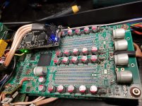
Did some late night worrying over the temps. Room temp 22-23C. Fully enclosed with slits only on the bottom, the top layer ladder seems to run at 50C at the hottest corner (closer to the 3.3V LDO). With lid open, the top ladder cools to 34C in the better areas and ~38C at the hottest corner, maybe affecting a few LSB in the left (inverted in dual mono) channel. The LDO is probably to blame for the slight imbalance as the entire area around it is quite hot. The bottom board after the lid is opened seems to be around 2-3C hotter than the top one at least around the vref opamp (I’m guessing the harder to measure regions have similar temp diff to the corresponding top board areas).
If slits are cut in the top/side panels, would temps be close to what I measured with top panel off?... how do people get around dust?... 5ppm for the 0.01% resistors yields 125ppm at 50C which is another 0.0125% it seems. Distortion and noise!
If slits are cut in the top/side panels, would temps be close to what I measured with top panel off?... how do people get around dust?... 5ppm for the 0.01% resistors yields 125ppm at 50C which is another 0.0125% it seems. Distortion and noise!
You better take acoustic feedback into account also - don't shake that clock!!!
//
What are you talking about - I love a good tune from MLCC peizoelectric effects.
Seriously, things are burning up. If only we had Z-foil resistors
$30 a piece is a pretty price thoHeck maybe I should just open my windows and regulate room temp at 0C. That ought to improve my listening sessions
————
Maybe I shouldn’t worry - 50C at worst turns 0.01% into 0.02%. Soren said long ago that different resistors measured about the same. Problem solved...
Last edited:
The error of a resistor due to the temperature is a well defined (in contrast to random) deviation curve (Delta-R over T).
As here the absolute value of the resistor does not matter that much as long the ratio is preserved, the temperature as such is no problem as long it is the same everywhere. Different temperatures of the resistor would matter.
As here the absolute value of the resistor does not matter that much as long the ratio is preserved, the temperature as such is no problem as long it is the same everywhere. Different temperatures of the resistor would matter.
The error of a resistor due to the temperature is a well defined (in contrast to random) deviation curve (Delta-R over T).
As here the absolute value of the resistor does not matter that much as long the ratio is preserved, the temperature as such is no problem as long it is the same everywhere. Different temperatures of the resistor would matter.
Temperature coefficients of quality thin film resistors usually follow a parabolic curve, so the max spec is usually at the extreme ends, which for the used resistors is -55 deg C and + 125 deg C, so a little elevated temperature is nothing to worry about....
All part of DIY!
Hope my reports can be of use to others deciding on the mod. Maybe Soren can help enlighten us on the theories
The goal is to get the vref impedance low over the whole frecuency range, the opamps take care of the low end, the ceramics take care of the high end, so adding electrolytic capaitors is to handle the mids.... More capacitors should have low ESR and low ESL, polymers are very good, so is large low ESR regular electrolytics....
It's a good thing to do simulations, assuming you have good models, you want to end with a constant low impedance over DC to 1M....
The error of a resistor due to the temperature is a well defined (in contrast to random) deviation curve (Delta-R over T).
As here the absolute value of the resistor does not matter that much as long the ratio is preserved, the temperature as such is no problem as long it is the same everywhere. Different temperatures of the resistor would matter.
I thought they could drift in different directions.. would be nice if ours happen to not do that though.
Temperature coefficients of quality thin film resistors usually follow a parabolic curve, so the max spec is usually at the extreme ends, which for the used resistors is -55 deg C and + 125 deg C, so a little elevated temperature is nothing to worry about....
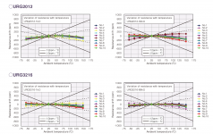
That's helpful information. I couldn't find much on thin film resistors but here're some measurements from Susumu parts. Note drifts in both directions. Though these thin films don't have the tight tolerance parabolic that Vishay metal foils do, it's fine I guess given the price point. It might be somewhat true that at temps closer to 25C TCR is a bit lower than spec and maybe a lot lower in some products. I would still recommend that temperatures be kept as close to 25C as possible, but unfortunately there's not much I can do in my build since I use buffered out which probably makes 9V DC minimum. Can't improve air convection much at the moment but if I ever get the chance I'll open up some slits on the top/side. There're slits on the bottom. But alas, who knows if this will create more imbalances... At least everything is probably equally toasty now.
Soren, are there TCR test curves for the resistors used in dam1021?
Sören, do you feel technically satisfied with the current products? If not, is it real-estate or cost that holds you back?
Where are you on the DC-1M situation?
//
Would like to know very much about this too.
Attachments
If you let air flow over the resistors, you will see distorsion.
//
That's definitely supposed to make me feel better about my build... Sigh, it does make sense and I believe you...
The other major heat sources in my build are the two transformers (12V 25W toroidal ~45C, SK Lite PCB transformer, possibly split-bobbin type, ~50C) and UltraBiB. Do you know if anyone ever found out whether the power draw is really constant? I put in 50% for peak draw as Soren suggested earlier in the thread but if I can cut on that maybe it'll cool the ladders by a couple of degrees due to a slightly lower internal temp.
Also, do you know if anyone tried to remove the power filter caps (and bridge rectifier)? I feel that more power output capacitance should probably be on UltraBiB not dam1021. Seems somewhat important with so much speculation on the sound of caps.
I will not hold my breath for an answer. Not for this one either: is the clock solution in the 1121 so tightly connected to the no_of filter taps really? Thinking FW...
//
You're so polite. Are you sure you don't want to try adding polymer caps to 1121?... I'm not 100% sure why it helps so much and for a while I was very worried that the greatly improved naturalness was due to noise somehow introduced by the caps (not that it sounds very scientific...). But when I stopped holding my breath and listened more carefully, I realized that all the micro-details are there, only perhaps I was accustomed to the harshness in the sound that's so easily taken for details.What are you talking about - I love a good tune from MLCC peizoelectric effects.
Seriously, things are burning up. If only we had Z-foil resistors
Heck maybe I should just open my windows and regulate room temp at 0C. That ought to improve my listening sessions
————
Maybe I shouldn’t worry - 50C at worst turns 0.01% into 0.02%. Soren said long ago that different resistors measured about the same. Problem solved...
The 3.3V regulation making that area of the board toasty is why I originally went with discrete regulators moved elsewhere, however that was when I was running 15V to them and they required active heatsinking. I since turned everything to 5V which allowed me to put the 3.3V regulators bare tabbed so they only feel warm to the touch.
If you don't use the buffered outputs then going +/-7V will also work and eliminate most of the 3.3V heat. (going to 5V requires further extensive modding, your own mute circuit, removal of mute transistors, the resistor that tells vref to disable, and finally bypassing of bridge rectifier and 7x05 regulators)
Last edited:
If you don't use the buffered outputs then going +/-7V will also work and eliminate most of the 3.3V heat. (going to 5V requires further extensive modding, your own mute circuit, removal of mute transistors, the resistor that tells vref to disable, and finally bypassing of bridge rectifier and 7x05 regulators)
Thanks for the info! Unfortunately I do use the buffers to drive headphones so will have to keep at 9V for a while... it would be nice to eventually get rid of the imbalances, though it’s only in the last few LSB. But I’m guessing even that won’t be the magic cure for my build heating issue
- Home
- Vendor's Bazaar
- Reference DAC Module - Discrete R-2R Sign Magnitude 24 bit 384 KHz