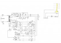
Could someone help me understand how this one relay (K401) works in this circuit? I don't understand how points 7,10, & 12 control this relay.
This looks to be a 4PDT DC24V Omron relay. Labelled K401 in the jpeg and highlighted yellow. The actual part has this writing on it : Omron Type MY4 -02-US-L DC24
The relay controls those 4 switches above it in yellow. They are shown in the off position. What they are switching was left out for clarity and it doesn't really matter. Except for the first switch, not sure what it is doing.
I wonder if I even need connection 7.
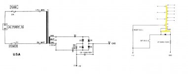
Ideally I just want one button to activate this relay from the power supply shown in the jpeg.
Any ideas on how to modify this circuit?
Thanks!
This looks to be a 4PDT DC24V Omron relay. Labelled K401 in the jpeg and highlighted yellow. The actual part has this writing on it : Omron Type MY4 -02-US-L DC24
The relay controls those 4 switches above it in yellow. They are shown in the off position. What they are switching was left out for clarity and it doesn't really matter. Except for the first switch, not sure what it is doing.
I wonder if I even need connection 7.
Ideally I just want one button to activate this relay from the power supply shown in the jpeg.
Any ideas on how to modify this circuit?
Thanks!
Attachments
Last edited:
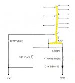
I found out that this comes from a standard latching relay circuit.
Check out this new revision, attached.
The momentary N.O. button when pressed will activated the relay and lock it on by using its own 1st switch. The momentary N.C. button will then reset the switches back to off when pressed.
Does this new circuit look right to you? Polarity ok? Buttons ok? Does that diode,resistor, and cap look right?
Any ideas?
Thanks!
Attachments
The capacitor stops contact bounce.Yes, it is correct.
There is also some kind of timer on the circuit.
The capacitor stops contact bounce.
Not only.
A diode does that job better.
")

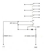
In the original circuit, the diode, resistor and capacitor has two effects: 1) it delays the operation of the relay slightly and 2) it extend the time the relay is pulled in. This may be critical to the operation of some other part of the circuit. True, the capacitor absorbs the flyback when the coil releases, but it is not the only function.
In the original circuit, the diode, resistor and capacitor has two effects: 1) it delays the operation of the relay slightly and 2) it extend the time the relay is pulled in. This may be critical to the operation of some other part of the circuit. True, the capacitor absorbs the flyback when the coil releases, but it is not the only function.
You are right, I said that in the third post.
Maybe it is negligible.
Just had a worry here. Do you think this setup will be ok with just push buttons like the latest jpg? I was wondering how long the relay takes to latch. Would it be possible to not push the buttons long enough to engage and disengage? This might be a problem if someone does not hold the button on long enough? Maybe this would be the reason for some capacitor setups, to have a minimum time.
Thoughts?
Thoughts?
Well the original design is for an entire reel-to-reel circuit. I only want to use this relay by itself.
I saw some Omron specs that say 20 ms max operating time and 20 ms max release time. If I'm understanding this correctly I think it is ok. I don't believe you can manually push the button faster than that.
I saw some Omron specs that say 20 ms max operating time and 20 ms max release time. If I'm understanding this correctly I think it is ok. I don't believe you can manually push the button faster than that.
- Status
- This old topic is closed. If you want to reopen this topic, contact a moderator using the "Report Post" button.
- Home
- Source & Line
- Analogue Source
- reel-to-reel Omron relay help