Hello,
I'm restoring an old amp and I'm intended to use a spare transformer I have (the high voltage secondary is 330-0-330V). I have performed some calculations with PSUD2 and to obtain the needed B+ voltages is sufficient having 330V rather than 660V at the plates of the rectifier tube (a 5Y3GT).
Rather than connecting 330V to pin 6 and 330V to pin 4 can I simply connect 330V to i.e pin 6 and the center tap 0V of the high voltage secondary to pin 4 (thus using only half of the winding so it would be 330V at the plates)?
Doing so I should not connect the other 330V to ground right?
Last edited:
What's your problem? Your transformer is designed for two-way rectification. Your 5Y3 is a two-way rectifier. So, connect each '330V' end to one of the 5Y3's plates, '0' to ground, and you'll get what you want from the tube's cathode.
Best regards!
Thanks for the reply. The problem is that doing as you suggest I have 660V at the plates of the 5Y3GT. I need 330V only at the plates (the power transformer is overpowered for the amplifier).
Last edited:
Thanks for the reply. The problem is that doing as you suggest I have 660V at the plates of the 5Y3GT. I need 330V only at the plates (the power transformer is overpowered for the amplifier).
This is not the case. 330V at each plate and the center tap to ground means that you get a rectified 330V at the cathode of the rectifier. Each plate 330V gets rectified at alternate mains phases, not added together.
Jan
Hello "Tano"
330V between plates or between plate and ground?
330V is needed between the plates. The transformer produce 330V between one end of the high voltage secondary and the high voltage secondary center tap.
This is not the case. 330V at each plate and the center tap to ground means that you get a rectified 330V at the cathode of the rectifier. Each plate 330V gets rectified at alternate mains phases, not added together.
Jan
Oh I see! I managed to measured the B+ produced having 660V between plates and indeed is not 800V but around 320V.
Thank you so much!
So in PSUD2 the voltage one inputs in the transformer section is not the total voltage across the plates but half of the high voltage secondary? Please see the attached picture.
Attachments
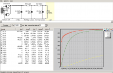
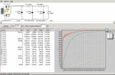
It's a bit tricky; it depends on the rectifier type you've selected.So in PSUD2 the voltage one inputs in the transformer section is not the total voltage across the plates but half of the high voltage secondary? Please see the attached picture.
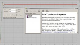
Not all the PSUD 'Help' is available from the top menu 'Help Contents' selection - the 'Help' buttons in individual 'Edit' windows provide more details.
Highlight the transformer, right click to 'Edit' and then the Help button will bring up the info you need.
It took me years to start to figure this out, so do not feel bad!
")
Attachments
- Status
- This old topic is closed. If you want to reopen this topic, contact a moderator using the "Report Post" button.
- Home
- Amplifiers
- Power Supplies
- Reducing plate voltage to the tube rectifier in full wave rectification.