")
Hello all,
I have had several requests for my version of the Leach Amp, but lost my original layout some time ago due to a hard disk failure (I will now be making weekly backups).
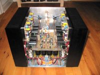
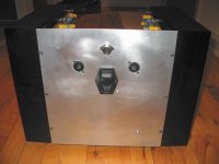
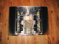
Anyway I have remade the layout on one board with room for 5 sets of output transistors and 10000uF 100V rail caps. (40mm diameter)
Let me know if anybody is interested in a group order for these, and also if you have any requests regarding the PCB.
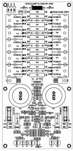
The PDF pic contains the layout, witch measures 120xx250 mm
\Jens
I have had several requests for my version of the Leach Amp, but lost my original layout some time ago due to a hard disk failure (I will now be making weekly backups).
Anyway I have remade the layout on one board with room for 5 sets of output transistors and 10000uF 100V rail caps. (40mm diameter)
Let me know if anybody is interested in a group order for these, and also if you have any requests regarding the PCB.
The PDF pic contains the layout, witch measures 120xx250 mm
\Jens
Attachments
modified leach amp
Hi JENs,
Your version of leach amp looks good , can I request you to provide me the pdf files of the leach amp so I can do this amp. (of course this is my dream amp).
1. you have used 5 pairs of Output pairs, what was the purpose, can it increase the power or you have done this to handle loads down to 2ohms.
2. what is the max voltage rail you recommend.
3. can I use 2sa1943 & 2sc5200 pairs.
4. can you provide some details of your modified version.
Thanks
Arasuk
Hi Arasuk,
>1. you have used 5 pairs of Output pairs, what was the purpose, can it increase the power or you have done this to handle loads down to 2ohms.
I have done this to be able to play into smaller loads and to increase the rail voltages while keeping a decent SOA for the output devices.
>2. what is the max voltage rail you recommend.
So far I have only tested it with +-55V, but I’ll be making tests with +-68V when I get the proto PCBs
>3. can I use 2sa1943 & 2sc5200 pairs.
YES! And MJL4281/4302
>4. can you provide some details of your modified version.
Small signal transistors are BC546/556
Vas and pre driver are MJE340/350
Drivers are MJE15034/15035
Extra decoupling caps on board along with zobel network and fuses.
The rest of the components are more or less the original, I'll be making a BOM later when everything is tested
\Jens
Modified leach amp!!
Hi Jens,
Thanks for the reply,
1. I remember Mr.Leach pointing out that +/- 58v is the best possible rail voltage. do you think Increasing it will lead for SOA problem.
2. Then using BC546/556 would not be probably better ???
3. About the short ckt prot what values do you reccomend,and have you tested with these values.
4.Does the "diode array" need to be implemented on the heat sinks??? can I replace them with some To220 type diodes or with an BJT.
thanks
Arasuk
>1. I remember Mr.Leach pointing out that +/- 58v is the best possible rail voltage. do you think Increasing it will lead for SOA problem.
I think he means for the setup with two transistors.
>2. Then using BC546/556 would not be probably better ???
I don't understand what you mean, please explain
>3. About the short ckt prot what values do you reccomend,and have you tested with these values.
I have tested them using +-55V, they need to be recalculated with +-68V!
>4.Does the "diode array" need to be implemented on the heat sinks??? can I replace them with some To220 type diodes or with an BJT.
You must place the diodes on the heatsink!! TO220 diodes could work well, for thermal tracking, not sure how the added cap to heatsink will influence the thing though
\Jens
From my simulations I don’t se a problem with the voltages exceeding the specs for the BC546/56 pair, but should there be a problem, I’ll just change to the MPSA92/42 pair. (They need to be rotated to fit the pinout, but I can live with that)
I will post the PDF’s needed for this project later, but first I need to verify a proto board as this is a new layout.
I will probably get some boards made, so if you are interested please let me know. Price will be around 60 US$ per board If I order 10. More boards will make it cheaper per board.
I am busy at work at the moment, so please be patient it will be some time before I can offer documentation.
\Jens
I think so too,
Preview
\Jens
Preview
An externally hosted image should be here but it was not working when we last tested it.
\Jens
Hi Jens,
I think I need to do the hard way to fix the Diode array, Coming back to the O/P Transistors I will go with 4 pairs.
I would redesign the Short Ckt for Load of 3 ohms , so that I dont have problems of the The sudden Kick in of the prot ckt.
I Think If i am not wrong, we can use BC 550/560 low noise transistor for the Input current mirros. This would be the best choice for the input stage, of course the remaining stays the same BC546/556.
lowering the value of R51 & Gnd Hum may be reduced,
Reduce the value for the base resistors,& DO you think I can Reduce The Emiter resistor value for 0.15 ohms with matched O/P pairs.
Thanks
Arasuk
Hi all,
slightly off topic, but since you all know the leach amp rather well here are my queries.
1. would leach be a good basis for a class A amp? I'm thinking 40v to 45v rails, Iq about 3amps and 4 output devices with the same device as the driver.
2. since the driver & output devices are running about 600ma, do I need fast output trannys say MJL1302 or would slower devices say MJ21193/4 be sufficient.
3.Can leach be modded to remove the dc blocking caps @ input and nfb and then use active feedback to zero the DC level at the output?
Lars, why the change to MJE15034/5? any disadvantage compared to 15030/1 or 15032/3
thanks in anticipation & regards Andrew T.
AndrewT,
Can't think of a good reason to try to mod this great amp into class A. I'm not an amp designer from scratch. However I have built and use a couple of the double barrelled versions that put out over 300 W and 4 of the regular Low TIM versions in my surround sound setup.
In addition, this from Professor Leach:
"Builders have asked me about increasing the amplifier bias current. I don't see any problems with this. However, I do not recommend any attempt to bias it class A. If it were biased class A for an 8 ohm load, the amplifier would quiescently dissipate a little over 600 W of heat from the heat sinks for the two channels. For a 4 ohm load, the bias current would have to be doubled so that two channels would quiescently dissipate a little over 1200 W. Not only is the amplifier power supply not designed to supply this power, but also the heat sinks are not large enough to dissipate the heat. If you want to know the effect on your electric bill, get an electric heater and run it the same number of hours a day that you run your amplifier. You will be paying double if you are running an air conditioner.
Some builders have told me that they wanted to increase the bias current because they didn't feel that the heat sinks felt warm enough to the touch. If you wish to increase the bias current, follow the biasing instructions to first increase it from the specified value of 100 mA to 150 mA. Use it for a while at low power levels, keeping tabs on the temperature of the heat sinks by feeling them occasionally. If you are using a cooling fan on the heat sinks, turn it off. If you want the heat sinks to feel warmer, increase the current to 200 mA and repeat the experiment. You do not want the heat sinks to feel hot to the touch when the amplifier is used at low power levels. When feeling the heat sinks, do not touch the output transistors. You can get shocked, especially if you simultaneously touch a NPN and a PNP transistor. They have about 116 V dc across them. "
For the complete dissertation from which I got this info, go to:
http://users.ece.gatech.edu/~mleach/lowtim/output.html
JensRasmussen said:I think so too,
Preview
An externally hosted image should be here but it was not working when we last tested it.
Your design looks very good, Jens.
Apparently there's a ground plane that is not designed here, so here goes a question. Are the grounds split into "clean" and "dirty" grounds to be joined at a star point?
If they are not, splitting them could get further benefits to the project.
Carlos
- Status
- This old topic is closed. If you want to reopen this topic, contact a moderator using the "Report Post" button.
- Home
- Amplifiers
- Solid State
- redesign of leach amp pcb for integrated TO-247 output devices