Add some smaller film caps in parallel with your main filter cap. Use like a 0.1uF and 0.01uF in parallel. That should clear up HF noise.
You probably don't want the caps directly across the diodes. Snubbers need a series resistance to work properly. I'd wager that 99% of the amps out there don't even bother with diode snubbers.
You probably don't want the caps directly across the diodes. Snubbers need a series resistance to work properly. I'd wager that 99% of the amps out there don't even bother with diode snubbers.
The HT diode switching transient has been shown to easily couple in to the heater winding and get amplified by the input stage - so yes that is highly likely to be the mechanism for noise injection.
I suggest you should remove the cap bypasses on the UF4007s, they just aren't needed, and may be exacerbating the problem. Adding a bypass cap across the HT winding itself, and/or adding some series resistance to the HT winding are likely to be your best path - and perhaps adding a bypass cap across the heater winding as close as possible to the transformer. The aim is to minimise dI/dt at diode switching spike, and constrain the energy in the leakage inductances to just the transformer windings.
Those scope traces were taken before I added the parallel caps, but the wave shape didn't change. What did change was the transient between the series diodes. Without the caps there's a very fast transient of about 15V (with the 5408's it was 75V!), with the caps there is only a sine wave with no high frequency transients.
Before I posted last night I had tried your suggestion of placing a cap between each HT to the CT, no effect. I had also tried a cap across the heater supply and from heater supply to ground, no effect. I was thinking of trying some series resistors before the diodes. How do I calculate their average power dissipation? The switching current is a big question mark...
Add some smaller film caps in parallel with your main filter cap. Use like a 0.1uF and 0.01uF in parallel. That should clear up HF noise.
You probably don't want the caps directly across the diodes. Snubbers need a series resistance to work properly. I'd wager that 99% of the amps out there don't even bother with diode snubbers.
I have tried various "smaller" value caps across the main reservoir, no effect. There isn't any high frequency noise on the DC. I think you're right, just took a look at the Soldano SLO100 schematic and it doesn't have any small value caps.
I really don't understand why I'm having so much trouble with this... looking at other design layouts I see longer loops than I have.
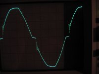
The flat-topping of your positive and negative sine wave is typical for the type of power supply topology you are using. It has nothing to do with snubbers at the rectifiers or transformer secondary. The flat-topping is due to two things:
a. Your electrical service has some flat-topping, as shown by your standby capture.
b. When under load, the transformer impedance is causing voltage drop of the secondary output. Saturation is NOT a cause- saturation will not look like this. Any windings that share the core will have a degree of additional flat-topping, but not as much as you see on the secondary- most of the voltage drop is across the DCR of the secondary.
NORMAL. Possible solutions to correct this is a choke input supply or larger transformer. Neither are necessary, as they are completely unrelated to the source of noise transients you are capturing. Let it be.
As far as the transients, these can be easily cleaned up by two methods:
1. Rectifier snubbing. You are not doing it properly. Without series resistance, a poly film cap is the absolute worst choice of snubber you could possibly use. In my experience with noise, rectifier noise is the lesser of two evils, so I would remove it for now until you incorporate method #2.
2. Transformer inductance kickback, which is easily corrected with an RC snubber. Again, without series resistance a poly is a terrible choice. You will find hundreds of people who disagree, and throw straight poly's all over their amps, so be prepared for the bad advice. I suggest a CDE 940C series cap, with suitable AC ratings. It goes across the secondary with a series resistor. Both resistor and capacitor size are determined by test with your scope (I used that exact model in the past and it works well). You need to zoom waaaaay in on the turn on/turn off regions of the voltage (and ideally look at current too if you have a clamp) and tweak both R and C values to completely eliminate it. Works like a charm. Absolutely noise-free power supply. I do not recommend using hagtech's method of calculating; too many variables when the scope is the final answer.
If you're serious about cleaning it up and are done throwing in straight caps, I can give further advice. But this is the fundamental starting point you need to begin with. Never use a straight film cap as a snubber.
If you're serious about cleaning it up and are done throwing in straight caps, I can give further advice. But this is the fundamental starting point you need to begin with. Never use a straight film cap as a snubber.
Thank you for your advice. I am 100% serious about cleaning it up since this noise is negatively affecting the sustain of the amp. Plus it just sounds awful when you stop playing or during quiet passages. Later today I hope to have time to wire in a different xfmr to power the heaters to prove that as the noise to signal injection point. Then I can get into coming up with some proper RC snubbers to solve this. Please feel free to send me a Private Message if you have some more tips on how to get this right.
I just read through this HagTech Calculating Optimum Snubbers and now I understand the theory, and agree that I don't have the equipment or information I need to do the math, so I'm going to have to try to use my crappy scope to figure out the frequency and fudge some values until I get it cleaned up.
Your cro photos show two types of rectifier noise. One is related to the transient spikes of very short duration at the instant of a diode turning off. Your change to faster diode, tidying up wiring, and indication that high frequency bypass caps on HT and heater winding don't change your noise issue, mean that this type of noise is now not your remaining (or possibly original) problem - even if you still see spikes on your cro waveforms.
The second type is introducing waveform distortion, and hence higher frequency mains harmonics that then couple through the heater winding and in to your input stage. You can try to alleviate the harshness of this type of distortion , which shows up as 'flat topping' (in addition to any flat topping that your mains waveform may have inherently) - which is usually done by lowering the filter C (ie. remove the extra C you added to get to 70uF), and adding extra HT winding R.
However Merlin has clearly shown that this type of heater induced noise ingress can be dramatically reduced by using a humdinger pot on the heater tuned to give minimal hum, and hence minimal injection of the heater voltage harmonic voltages in to the grid of the input valve. I suggest this is your best first activity.
Wrt to snubbing across the HT secondary winding - placing a simple small C (eg. 1-10nF) is simple, and inherently works with the usually significant series resistance of a HT winding (eg. a few hundred ohms). The damping of this simple bypass may not be optimal, but its simplicity, and aim of reducing the loop area of the noise current current, is a simple winner for that type of noise alleviation.
trobbins, I've tried a few values of caps across the secondary windings with no effect.
When you say "adding extra HT winding R" do you mean add some small series resistance to the secondary of the xfmr before wiring to the diodes?
I have the heaters elevated to 70Vdc. If I were to add a humdinger, would I wire the wiper to that 70Vdc reference and lift the xfmr CT from that reference?
Even with elevated DC heater, the coupling is from the heater winding voltage at the exposed ends of the heater, coupling to the grid at the tube itself - the humdinger attempts to balance any asymmetry in the heater voltage seen at the grid from each end of the heater so they null at the grid. The wiper of the pot goes to the elevated DC supply (rather than use humdinger fixed resistors), or remove the heater CT connection to the elevated dc and use the pot arms to connect to the heater.
Yes, extra HT winding series resistance helps to smooth out the abrupt clamping of the output capacitor when the diode conducts - the charging current waveform of the HT winding is smoothed out. You can reverse-engineer from say a 5W resistor, with a max rms power loss of 2W, and simplistically use half the DC supply loading max current as a ballpark for the added resistor rms current (if using a CT type valve rectifier HT winding configuration).
Yes, extra HT winding series resistance helps to smooth out the abrupt clamping of the output capacitor when the diode conducts - the charging current waveform of the HT winding is smoothed out. You can reverse-engineer from say a 5W resistor, with a max rms power loss of 2W, and simplistically use half the DC supply loading max current as a ballpark for the added resistor rms current (if using a CT type valve rectifier HT winding configuration).
Simple procedure to start with:
1. Remove all rectifier snubbing.
2. Connect scope common to HT center tap. I assume this is somewhere bonded to the amp chassis, so should be safe. 10X scope probe to one end of the HT secondary. Attached is an example of a really bad case of inductive ringing. Note it happens at both turn-on and turn-off, but one may be worse than another. Note also this was eventually smoothed out like a baby's bottom with NO rectifier snubbing.
3. Run the amp and set the scope to zoom way in on the switch-on spike. This is important. You want to fill the screen completely with just the turn-on ringing. Your scope is able to do this. Play around with vertical/horizontal position, timebase and vertical sensitivity, and trigger level.
4. Put on leather gloves. A little caution is a good thing.
5. Set up an RC network consisting of a 0.01uF poly (ideal) or ceramic (acceptable) in series with a 10k pot. There will be flying leads attached to this network to enable easy adjustment and connection to the secondary. Connect to either end of the secondary (not to the CT). Begin with the pot in 10k. Be sure your capacitor is able to support the AC voltage involved. This is why I have a bucket of 5 different sized CDE 940C caps at the higher voltage ratings.
6. You should be able to easily see how adjusting the pot affects the ringing. Obviously the goal is to eliminate over shoot and ringing completely, but this is not always perfectly possible. Sometimes you have more than one characteristic frequency to contend with, but I have found one RC is sufficient.
7. Don't leave the pot in the 0 position very long; you are only trying to identify ballpark values at this point.
8. Try increasing to 0.022 uF and repeat. You can now get an idea if a larger cap is providing better results or essentially the same. You want to pick the smallest cap possible to get the job done, while also avoiding having the pot at the zero position.
9. Between 0.01 and 0.047 uF seems to be the sweet spot for the size transformers and voltages typical in valve amps.
10. Once you have identified the smallest capacitor that will work, set the pot to provide just enough damping to snub the ringing. More is not always better (nor is guessing and just throwing in caps without measurement).
11. Replace this pot with a 1/2W carbon comp resistor and solder in with shortest leads possible. Expect the value to be greater than a few hundred ohms.
This only corrects one of many issues. After that, you can look into whether or not your rectifiers need snubbing (which I highly doubt). I will say you are better off with a UF4007 than a 1N4007.
After that you can investigate improvements to the heater circuit. Separate xfmrs are best, but if that doesn't fit in the chassis I would pursue high leakage common mode chokes with ceramic caps right at the heater pins. But one thing at a time, get rid of inductive kick from the power transformer.
Attachments
I've done some investigation, and I can see 85kHz noise on the heater supply. I can't zoom in far enough on the HT because the scope doesn't let me offset far enough to be able to scale down enough to see. I just tried 1nF poly cap in series with a 2k resistor, from each leg of the HT secondary to its CT, no effect. f-cutoff of that combo should be about 80kHz. I've probably forgotten about L of the secondary, but this is an unknown. From anyone's past experience, is there some rule of thumb I could go by? I really hate this random stabbing at the problem. From these values I don't even know if I should go up or down in value...
Last night I tried 15 ohms series with each leg of the HT before the diodes and I did see an improvement. This along with 1nF across each rectifier diode is the only thing that has shown improvement so far.
Last night I tried 15 ohms series with each leg of the HT before the diodes and I did see an improvement. This along with 1nF across each rectifier diode is the only thing that has shown improvement so far.
zigzagflux, we just posted at the same time. I read your post after mine. I will try your process later today, thank you!
I only keep saying my scope is crappy because I brought it home from work, where we have some very nice scopes that I can't afford to risk bringing home.") The old TDS220's at work have pretty much been relegated to yes or no type of measurements.
The old TDS220's at work have pretty much been relegated to yes or no type of measurements.
I only keep saying my scope is crappy because I brought it home from work, where we have some very nice scopes that I can't afford to risk bringing home.
The old TDS220's at work have pretty much been relegated to yes or no type of measurements.I just read through this HagTech Calculating Optimum Snubbers and now I understand the theory, and agree that I don't have the equipment or information I need to do the math, so I'm going to have to try to use my crappy scope to figure out the frequency and fudge some values until I get it cleaned up.
I posted the practical method for determining snubber component values at the link below:
http://www.diyaudio.com/forums/powe...lm-caps-electrolytic-caps-30.html#post2828689
I would not expect a 1 nF to be large enough, but it is a starting point. Go up from there, but it won't be more than 1 uF.
If you have a dearth of high voltage caps, you can even do the snubbing on the 120VAC primary winding, though I much prefer to snub at the source of the switching (close to the rectifiers).
Oh yeah, one other thing: turn off as much other 'stuff' in your house as practical. Keep fluorescent lights unplugged. Just for this procedure, to make sure you are snubbing the amp, not some other device.
Last edited:
3. Run the amp and set the scope to zoom way in on the switch-on spike. This is important. You want to fill the screen completely with just the turn-on ringing. Your scope is able to do this. Play around with vertical/horizontal position, timebase and vertical sensitivity, and trigger level.
I cannot find ringing near the switching point, nor anywhere along the slope of the HT. The only distortion of the HT that I can find is at the +/- peaks.
I tried 0.01uF, 0.022uF and 0.044uF (I only have 0.001, 0.01 and 0.022 rated 1kV or higher) watching the 85kHz noise on the heater supply, and listening to the amp noise. There was definitely a change, but I was unable to significantly reduce the noise. It seems that it was a lot easier to increase the noise (as the pot reduced to 0) than reduce the noise.
I'm now wondering if I'm not chasing the real problem. What else could be causing such flat-topping of the HT and heater supply?
The last picture in this post shows the heater voltage when the HT is on standby (standby is in the "standard" position for guitar amps, cuts the connection between the main reservoir cap and the CT of the output xfmr). I also have a half power switch that lifts the cathode from one pair of 6V6's. The noise is reduced with the lower load, but still loud enough to be troublesome.
Can you show the 85 kHz noise? That is not originating from the amp, it is probably from a ballast in your house somewhere (fluorescent lightning). 85 kHz is also likely not audible.
Your heater voltages before and after load do not look all that terrible. You might have to begin characterizing what it is you are hearing as far as noise. Is it hum, buzz, or high frequency hash?
If you cannot find any switching transients on the HT, that is good news, but I will say with my scope every power supply I ever built, choke or cap input, had some degree of ringing that I could detect. Maybe you are lucky.
So snubbing may not be what you are trying to resolve. Are you certain you unplugged as much in your house as possible, just to eliminate the obvious? Do you use fluorescent lighting anywhere ?
- Status
- This old topic is closed. If you want to reopen this topic, contact a moderator using the "Report Post" button.
- Home
- Amplifiers
- Tubes / Valves
- Rectifier injecting noise into heater supply