ok, I've followed your advice and this is what I have right now. Does this look proper?
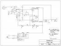
In the second image, will it work to add another RC filter in order to bring down the output screen voltage a little lower than the 12at7 plate voltage? See R12 & C9....
In the second image, will it work to add another RC filter in order to bring down the output screen voltage a little lower than the 12at7 plate voltage? See R12 & C9....
Attachments
Last edited:
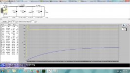
That's good. Now you can see that you have a lot of ripple on C2. Try raising C1 to 40uF and C2 to 100uF or 200uF. You can zoom in to see the waveform more clearly.
You can model you screen supply with another current tap that will probably be only 3mA; so you will have three current taps separated by two RC networks in series.
You can model you screen supply with another current tap that will probably be only 3mA; so you will have three current taps separated by two RC networks in series.
Ok, playing around with the PSUD a little more. For guitar amp applications, what is an acceptable amount of ripple... 1v? .5v? Less, more? Just trying to get an idea of what is reasonable.. One thing to note, I don't like my amps sounding too "tight".
--------------------------------------------------
IMHO : In Push Pull, high quality audio, B+ to the FINALS, you are OK with 2 VAC of ripple. To the front end, it is nice to have 2 mVAC of ripple.
In SE, high quality audio, you can get by with as much as 600 mVAC ( .6 VAC ) of B+ ripple to the Finals. Front end, shoot for 1 or 2 mVAC.
*** Ripple reduction is over-rated by most amateurs as a design goal !!!
--------------------------------------------------
A second question, What are those wavey patterns that smooth out from left to right? They take up more of the graph in the second image with another filter added on. Is this a graph that accounts for time and that is what the forms look like when it's first switched on?
---------------------------------------------------
In the second input box, you can add a DELAY for the simulation to start, so you are not tracking those initial turn on transients ( wavy wild lines ). I usually put a 4 second delay in, so voltages settle out. TRY it and you will see. Have fun !!
Jeff
- Status
- This old topic is closed. If you want to reopen this topic, contact a moderator using the "Report Post" button.