I'm not sure what the point is of the previous posts - what is the VAS circuit, input overdrive levels? - voltage clipping may be "unintersting" when output current limitation is an issue
also sq wave may not reveal all clipping artifacts - the fast edge in recovery may zoom right past stickiness or oscillation bursts that a slower slew rate out of clipping would show
also sq wave may not reveal all clipping artifacts - the fast edge in recovery may zoom right past stickiness or oscillation bursts that a slower slew rate out of clipping would show
Last edited:
The dynamic headroom of a chorus of some 100 singers is 120dB ... so what matters in terms of clipping is the dynamic headroom of the source. If you figure 70 dB and assume
30 dB to be achieved with 10 milliwatts then 70 dB is equivalent to 100 watts... for LPs you have to consider crest factors and whoopie...then non clipping requires 300 watts.
This is not all you have to consider far more in terms of physics of semiconductor devices.
It appears if MOSFETs are driven properly (!) these devices should have less problems
in recovery from clipping than BJTs.
I'm not sure what the point is of the previous posts - what is the VAS circuit, input overdrive levels? - voltage clipping may be "unintersting" when output current limitation is an issue
also sq wave may not reveal all clipping artifacts - the fast edge in recovery may zoom right past stickiness or oscillation bursts that a slower slew rate out of clipping would show
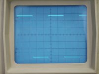
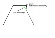
such as this common clipping problem, "overhang" is one name for it, and it's caused by the output devices being in saturation too long:
Attachments
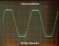
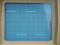
My latest, measured today. 8 ohm load.
Pavel at what freq is this? (Looks good btw).
jd
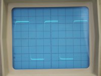
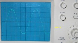
Jan, it is at 1kHz. Square for same freq., at 40us/div:
Ahh, I'm not impressed by square waves. Once you filter them at 20 or 30kHz to emulate real music, they all look the same anyway.
")
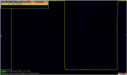
But that soft clipper is really good. How does it do at 10 or 20kHz?
jd
Upupa & PMA,
beautiful!
Hi Upupa,No other similar pics all around the world ? Or this behavior of amp isn't interesting for you ?
are you asking me?
That is a complement to both of you.
I wish you had the time and enthusiasm to teach us how to emulate that performance.
No Andrew, it was common question for all...
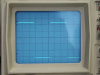
Principle of this circuit is quite simply: find at schematic Q17, D8 and D5. At collector of Q17, which is one half of VAS, you have AC voltage. By normal AC condition is D8 closed, 'cos at cathode is higher voltage than at anode. But if voltage at collector of Q17 rise at value near of clipping, this diode turn on and drop output voltage into base circuit, i.e. amplify of this stage fall to one, which cause that OLG rapidly fall down and saturation of this stage ( which is caused by " normal " condition by high OLG ) is much more lower. Voltage drop at D5 shift point of switching to the optimal ( lower ) value. Diode D8 must be of switching type ( by lower rail voltage 1N4148, by higher BAV20 or 21 ). That's all, result of this circuit you saw at pics...
Principle of this circuit is quite simply: find at schematic Q17, D8 and D5. At collector of Q17, which is one half of VAS, you have AC voltage. By normal AC condition is D8 closed, 'cos at cathode is higher voltage than at anode. But if voltage at collector of Q17 rise at value near of clipping, this diode turn on and drop output voltage into base circuit, i.e. amplify of this stage fall to one, which cause that OLG rapidly fall down and saturation of this stage ( which is caused by " normal " condition by high OLG ) is much more lower. Voltage drop at D5 shift point of switching to the optimal ( lower ) value. Diode D8 must be of switching type ( by lower rail voltage 1N4148, by higher BAV20 or 21 ). That's all, result of this circuit you saw at pics...
Attachments
- Status
- This old topic is closed. If you want to reopen this topic, contact a moderator using the "Report Post" button.
- Home
- Amplifiers
- Solid State
- Recovery from clipping, soft clipping