A Stitch In Time Saves Nine....
Yes, from what I have seen, you are wise to follow up on this before it gets expensive - maybe change the trimpots too.
Also the internal audio cable could stand upgrading imo.
With one of these for subs you ought be be able to break your walls down, and those neighbours will be wishing that they were time transported.")
Eric.
Yes, from what I have seen, you are wise to follow up on this before it gets expensive - maybe change the trimpots too.
Also the internal audio cable could stand upgrading imo.
With one of these for subs you ought be be able to break your walls down, and those neighbours will be wishing that they were time transported.
Eric.
Re: A Stitch In Time Saves Nine....
I'm reluctant to change the trimmers unless I know what the voltages at that part of the circuit <i>should</i> be. I know I can measure it beforehand, but I don't know what's there now is correct.
Could that be one of the reasons they're moving? When the real estate agent rings and says they're bringing someone to look at the place, she comes over and asks me not to play the system for a little while.
mrfeedback said:Yes, from what I have seen, you are wise to follow up on this before it gets expensive - maybe change the trimpots too.
Also the internal audio cable could stand upgrading imo.
I'm reluctant to change the trimmers unless I know what the voltages at that part of the circuit <i>should</i> be. I know I can measure it beforehand, but I don't know what's there now is correct.
With one of these for subs you ought be be able to break your walls down, and those neighbours will be wishing that they were time transported.
Could that be one of the reasons they're moving? When the real estate agent rings and says they're bringing someone to look at the place, she comes over and asks me not to play the system for a little while.
Do It Right....
What a big wuss.
One is DC offset - easy to work out which one by inspection, and the other will be 'you guessed it' BIAS current adjustment.
1) - Carefully mark all trimpots.
2) - Put an ammeter across one of the (say positive) DC fuseholders (both positive fuseholders if you have 2 ammeters) and WRITE the readings after achieving thermal equilibrium.
3) - Measure the DC offsets with inputs shorted and no loads.
4) - Carefully tweak the bias pots and note which direction causes diminishing of bias current, and mark the board accordingly.
5) - Shut the thing down, and when the supplies have decayed, replace the trimpots OR twiddle them back and forth to clear any noisey contacts.
6) - Reset the DC pots to the markings, and set the BIAS current trimpots to the minimum bias setting position.
7) - Bring the bias current back up to the previously measured values in stages, allowing time to reach thermal stability each step.
8) - Do steps 1 through 7 for the other channel.
In my experience trimpots are not always reliable and can go noisey.
I never let an amp out without changing them, or at least rotating them 20 times, and optional contact oil treatment.
'Select on test' bias setting fixed resistors can be tedious to get right, but are worth the effort long-term.
Do this treatment and my earlier advice, and it'll never let you down.
Cheers, Eric.
PS - Brett, I hope you don't mind me explaining this to you in such detail, but I think you told me that you were once a Broadcast Technician, and not a R&R Technician.
I'm reluctant to change the trimmers unless I know what the voltages at that part of the circuit should be. I know I can measure it beforehand, but I don't know what's there now is correct.
What a big wuss.
One is DC offset - easy to work out which one by inspection, and the other will be 'you guessed it' BIAS current adjustment.
1) - Carefully mark all trimpots.
2) - Put an ammeter across one of the (say positive) DC fuseholders (both positive fuseholders if you have 2 ammeters) and WRITE the readings after achieving thermal equilibrium.
3) - Measure the DC offsets with inputs shorted and no loads.
4) - Carefully tweak the bias pots and note which direction causes diminishing of bias current, and mark the board accordingly.
5) - Shut the thing down, and when the supplies have decayed, replace the trimpots OR twiddle them back and forth to clear any noisey contacts.
6) - Reset the DC pots to the markings, and set the BIAS current trimpots to the minimum bias setting position.
7) - Bring the bias current back up to the previously measured values in stages, allowing time to reach thermal stability each step.
8) - Do steps 1 through 7 for the other channel.
In my experience trimpots are not always reliable and can go noisey.
I never let an amp out without changing them, or at least rotating them 20 times, and optional contact oil treatment.
'Select on test' bias setting fixed resistors can be tedious to get right, but are worth the effort long-term.
Do this treatment and my earlier advice, and it'll never let you down.
Cheers, Eric.
PS - Brett, I hope you don't mind me explaining this to you in such detail, but I think you told me that you were once a Broadcast Technician, and not a R&R Technician.
A Full Job Is A Good Job.
Not sure, because I have not worked on a P200.
The above procedures I perform on all old high power (and low power) amplifiers that come over my repairs bench, and that way when I send them out I know that they are working at their optimum, and they should be completely reliable, and touch wood so far, I NEVER get the same amp back.
I repair high power amps for band PA systems usage, and my customers are happy to pay extra for a complete repair - an amp going down mid-show is not good for my customers.
I insist on this approach on old amplifiers because I do not want them coming back under workshop warranty with expensive blown outputs, and this method works for me and the customers.
I also find that a newly resoldered amp sounds much better too.
Eric.
TO NH7RO & All!!!!
Hello!,
Just a large word of warning about the use of Nichicon caps. I work for one of the largest suppliers of automotive electronics in the USA. We have found these caps to be VERY likely to leak on to Your PCBs. I have found that, in My experience here and In My Own business, that ANY Nichicon caps are better off being replaced.
Respectfully,
Tall Shadow
NH7RO said:Bingo! Eric, that 100uF LF rolloff cap in the right channel was the culprit. I replaced it with a Nichicon 35v electro and now the amp is back to normal--great bass in both channels. I also cleaned the boards well and got a lot of flux off!
Cheers! Jeff
Hello!,
Just a large word of warning about the use of Nichicon caps. I work for one of the largest suppliers of automotive electronics in the USA. We have found these caps to be VERY likely to leak on to Your PCBs. I have found that, in My experience here and In My Own business, that ANY Nichicon caps are better off being replaced.
Respectfully,
Tall Shadow
Re: Do It Right....
Thanks Eric, but that's similar to what I would have done anyway for a pot replacement. Your not entirely correct on one point: I've done plenty of PA amps before, and always used the approved and recommended technique. All an R&R tech need to know is, hose out the beer, dry it off, hit it twice with a large rubber mallet for luck, and send it back out. But your method only returns it to where it is now after pot replacement, and doesn't address my original point of wanting to know what it should be as per factory specs.
And y'see, this is <i>my</i> amp, and it's powering <i>my</i> expensive speakers, so I'm a tad fussier. A schematic will turn up.
mrfeedback said:PS - Brett, I hope you don't mind me explaining this to you in such detail, but I think you told me that you were once a Broadcast Technician, and not a R&R Technician.
Thanks Eric, but that's similar to what I would have done anyway for a pot replacement. Your not entirely correct on one point: I've done plenty of PA amps before, and always used the approved and recommended technique. All an R&R tech need to know is, hose out the beer, dry it off, hit it twice with a large rubber mallet for luck, and send it back out.
But your method only returns it to where it is now after pot replacement, and doesn't address my original point of wanting to know what it should be as per factory specs.And y'see, this is <i>my</i> amp, and it's powering <i>my</i> expensive speakers, so I'm a tad fussier. A schematic will turn up.
Re: TO NH7RO & All!!!!
Thanks guys for your Nichicon alert--it was all I could find locally out here on this rock (Hawaii) for a temporary tryout. I still plan to round up some Hitano EXRs and replace ALL the electros but will have to send off to Australia to do so. Anyone here know of any USA source for Hitanos? My thanks again! Jeff
Tall Shadow said:
Hello!,
Just a large word of warning about the use of Nichicon caps. I work for one of the largest suppliers of automotive electronics in the USA. We have found these caps to be VERY likely to leak on to Your PCBs. I have found that, in My experience here and In My Own business, that ANY Nichicon caps are better off being replaced.
Respectfully,
Tall Shadow
Thanks guys for your Nichicon alert--it was all I could find locally out here on this rock (Hawaii) for a temporary tryout. I still plan to round up some Hitano EXRs and replace ALL the electros but will have to send off to Australia to do so. Anyone here know of any USA source for Hitanos? My thanks again! Jeff
Renovated Means Renovated.
I know that PA amps will withstand a persuasive mallet hit, but I don't dare send them back out half done - if they fail mid show I get my butt kicked, plus I have to fork out for new parts.
I prefer to do it properly in the first case.
By the sounds of it you have worked with too many shonky R&R technicians.
I have worked with a few shonky Broadcast Techs too - if they don't have a circuit manual they can't work it out, or if they can they'll take all day - those kinda guys are no use to me in my repair business. - Sheltered Workshop techs we call them.
I mean, when I renovate any big amps I change pcb elecros, maybe trimpots, whatever is blown, blanket resolder, clean the boards and then cal bias and dc offset - I reckon that is a pretty complete job, and they don't come back under workshop warranty.
If I do not have bias current specs, I measure bias both channels and make an informed decision on where to set both channels.
Dc offset is of course 0V wrt to - speaker terminal.
I usually have a listen whilst adjusting bias within sensible range, and listen if there is any sonic difference - usually not much.
The preferred method would be to run thd and imd measurements at a range of bias currents.
For big amps I tend to slightly underbias them in the interests of reliability - at some outdoor summer shows (40*C days) the amp racks can get too hot to keep your hand on.
For home listening, finely adjusting the bias current is practical.
Eric.
You forgot the fog-juice and the roaches.All an R&R tech need to know is, hose out the beer, dry it off, hit it twice with a large rubber mallet for luck, and send it back out.
I know that PA amps will withstand a persuasive mallet hit, but I don't dare send them back out half done - if they fail mid show I get my butt kicked, plus I have to fork out for new parts.
I prefer to do it properly in the first case.
By the sounds of it you have worked with too many shonky R&R technicians.
I have worked with a few shonky Broadcast Techs too - if they don't have a circuit manual they can't work it out, or if they can they'll take all day - those kinda guys are no use to me in my repair business. - Sheltered Workshop techs we call them.
Hi Brett,But your method only returns it to where it is now after pot replacement, and doesn't address my original point of wanting to know what it should be as per factory specs.
I mean, when I renovate any big amps I change pcb elecros, maybe trimpots, whatever is blown, blanket resolder, clean the boards and then cal bias and dc offset - I reckon that is a pretty complete job, and they don't come back under workshop warranty.
If I do not have bias current specs, I measure bias both channels and make an informed decision on where to set both channels.
Dc offset is of course 0V wrt to - speaker terminal.
I usually have a listen whilst adjusting bias within sensible range, and listen if there is any sonic difference - usually not much.
The preferred method would be to run thd and imd measurements at a range of bias currents.
For big amps I tend to slightly underbias them in the interests of reliability - at some outdoor summer shows (40*C days) the amp racks can get too hot to keep your hand on.
For home listening, finely adjusting the bias current is practical.
Eric.
Nah, I never found the paper schematic I had.
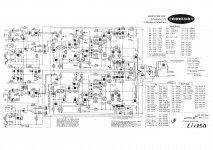
I did recently hunt down (Google) a pdf of 6200B schematic which I think is damn close to the 6000B amp that I have on my bench right now...6200 has 2 less output transistors and lower rail voltages than the 6000B but essentially the same amp I think without close inspection.
If you neeed 6200B schematic PM me and I will send it to ya.
Eric.
Thank you
Hi Eric,
Thank you for responding, I was able to get a schematic from Perreaux, which i will post here soon for others who might need it.
If I may ask a question, one side of my 6000B starts to clip and the red clipping light comes on, the other side goes all the way full with no problems. the clipping side is still pretty darn loud and clean till a certain point. Would you have any suggestions for that cause?
I have ordered new electrolytics for both sides, and have been reading over several times this thread with your tips and am very thankful for that.
Thanks again for responding,
Eric Pinson
Replace the caps and see how you go....
Funnily enough, I have a 6000B on the bench right now and have just replaced amp board input cap (10uF 63V) with a non-polarised electro and replaced the dc unity gain cap (220uF 63V) with a low esr version and the amp now sounds a little cleaner.
Next step is to replace the electros on the balanced input board with new.
After that I will desolder all amp board wire connections, remove four bolts per side and remove both modules for the blanket resoldering/cleaning operation.
After that is to tin all wires leaving a blob of solder and then sweat the wires back to where they belong on the pcb.....better than brand new amp !.
If you could fling me a copy of your 6000B manual that would be much appreciated.
Regards, Eric.
- Status
- This old topic is closed. If you want to reopen this topic, contact a moderator using the "Report Post" button.
- Home
- Design & Build
- Parts
- Recapping a Perreaux 1150B amp?