Hi all,
I'm a newbie and need your help for rebuilding the PSU of my Counterpoint SA-5.1. This is what I'm talking about:
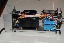
And this is the schematics for it. Remember, Counterpoint schematics are known to be different then what is really inside. That's the beauty of owning a Counterpoint
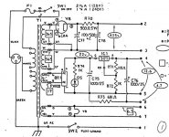
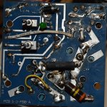
My starting point was to replace the first 100uf cap with a smaller value cap due to recommendations of Counterpoint experts here. As you see in the schematics, that cap is the first cap after the 6CA4 rectifier, and exceeds the datasheet values of 6CA4 tubes. Searching for a cap is slippery surface when you have little criterias. At some point I decided to use a film cap at due to the small PSU chassis of SA-5.1 I decided to built a new one from the beginning. This is the original PCB of the PSU. It had some works on it, left from the previous owners:
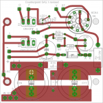
I'm lucky enough to have a new designed PSU board by our member Pars. He made some corrections to the original design. I'm planing to use this board on my rebuilt:
In my built I'll use a bigger chassis than this one, so I'll have plenty of place.
One of the changes I'm planning is the circuity at the main power switch. SA-5.1 is always on, to keep the heaters powered whenever the preamp is plugged in. The power switch controls the power to the heater on the rectifier tube only, which then powers up the HV section, and turns the preamp on. Our member VivaVee and Pars suggested a delay circuit which will turn on the heater immediately and HV section after a delay. VivaVee also suggested the Morgan Jones book but I'd be glad to hear any more help.
I'll change the electrolytic capacitors to film caps, add a IEC plug to the back. I may consider to omit the PCB and convert it to a point-to-point wiring, but I'm not experienced enough to do that.
Since there is a big transformer along with a 6AC4 tube in this case I want to add a thick enough case on the xfrmr to shield it. BTW, I'll use a Plitron toroidal xfrmr in the new PSU. I ordered Ott's book and looking for a bargain copy of Morrison's book.
Ok, let this be a start to the topic. I hope the helpful people on this forum join to this conversation.
Regards,
I'm a newbie and need your help for rebuilding the PSU of my Counterpoint SA-5.1. This is what I'm talking about:

And this is the schematics for it. Remember, Counterpoint schematics are known to be different then what is really inside. That's the beauty of owning a Counterpoint

My starting point was to replace the first 100uf cap with a smaller value cap due to recommendations of Counterpoint experts here. As you see in the schematics, that cap is the first cap after the 6CA4 rectifier, and exceeds the datasheet values of 6CA4 tubes. Searching for a cap is slippery surface when you have little criterias. At some point I decided to use a film cap at due to the small PSU chassis of SA-5.1 I decided to built a new one from the beginning. This is the original PCB of the PSU. It had some works on it, left from the previous owners:

I'm lucky enough to have a new designed PSU board by our member Pars. He made some corrections to the original design. I'm planing to use this board on my rebuilt:

In my built I'll use a bigger chassis than this one, so I'll have plenty of place.
One of the changes I'm planning is the circuity at the main power switch. SA-5.1 is always on, to keep the heaters powered whenever the preamp is plugged in. The power switch controls the power to the heater on the rectifier tube only, which then powers up the HV section, and turns the preamp on. Our member VivaVee and Pars suggested a delay circuit which will turn on the heater immediately and HV section after a delay. VivaVee also suggested the Morgan Jones book but I'd be glad to hear any more help.
I'll change the electrolytic capacitors to film caps, add a IEC plug to the back. I may consider to omit the PCB and convert it to a point-to-point wiring, but I'm not experienced enough to do that.
Since there is a big transformer along with a 6AC4 tube in this case I want to add a thick enough case on the xfrmr to shield it. BTW, I'll use a Plitron toroidal xfrmr in the new PSU. I ordered Ott's book and looking for a bargain copy of Morrison's book.
Ok, let this be a start to the topic. I hope the helpful people on this forum join to this conversation.

Regards,
Hi,
An old post, but I will answer.
Remove the heater trace between the tube pins. Too high a voltage differential. Use wire to pads next to the heater pins.
Lower the capacitance, as you've been told. Always believe the data sheet abs max ratings. This supply has no need of extremely high capacitance. Allow some sinus ripple, that is far less trouble than a high frequency sawtooth. Removing the rectifier heater line from the cable is an excellent idea, use the timing circuit. Don't run the heaters when the unit is off either. That practice will poison cathodes and might make the grids emit electrons, depending on the tube manufacturer.
I would keep to the same case. If you don't, you may as well build a better design. The existing preamp has value that you can sell for funds.
-Chris
I'm also rebuilding a 5.1 power supply. The one in my possession has a shorted AC transformer which needs to be replaced. Is the Plitron toroidal worth the money and, if so, does anyone have the part number or specs to use when ordering? Alternatively, can anyone provide the specs for a beefed-up replacement of the original bell-end style or have one to sell?
Thanks!
Joe
Thanks!
Joe
I was able to come up with specs for a better drop-in replacement. For others who may need one, they are:
EI Core
Primary: 117V @ 60Hz (or whatever your native current is)
Secondary 1: 365-0-365 @ 100mA
Secondary 2: 17V @ 3A
Secondary 3: 6.3V @ 4A
I ordered one from Heyboer Transformers in Grand Heven, Michigan, USA, for $120, delivered to me in New York (a bargain!). They're fabricated to order and lead time is a month.
Links:
Heyboer Transformer - Top
or contact Arlyn Arendsen:
arlyn@heyboertransformers.net
Thanks,
Joe
Going along with this SA-5.1, i used to own one also very nice preamp. One of the coolest things on the counterpoint line was the bicolor led that would go from red to orange and then full green when the preamp had warmed up for use. Does anyone have the schematic for that led circuit or know how to accomplish the same thing?
I was able to come up with specs for a better drop-in replacement...
I was discussing Counterpoint components with another hobbyist who said that Counterpoint's original transformers often failed because they were under rated for the component's current draw and may have been updated over the life of the product in a different size. If you're in a situation that requires a replacement power transformer, it's best to measure yours and send it with a photo to whatever firm is supplying the replacement. The measurements mentioned above may or may not match the transformer in your own PSU. Take nothing for granted!
RC
Hi Freecrowder,
That is just a green-red bi-colour LED. All they did was to turn both sections on at once.
Hi romana,
I didn't see that many preamp transformers go. This was more the power amplifiers. However, they did have QC issues with their own transformers. If you reduce the filter capacitor size for the B+, that should help. The heater, well a switching supply would help a little, not much. The better materials in a new transformer will also help (lower losses).
You'd really have to make the core a little larger to make a big difference, and identical rated and sized transformers made by Heyboer have run fine. They may even have the specs for these on file. I do know they can make you one. Just as tourists mentioned above. If it were me, I'd buy one from Heyboer and be done with it.
One of the coolest things on the counterpoint line was the bicolor led that would go from red to orange and then full green when the preamp had warmed up for use. Does anyone have the schematic for that led circuit or know how to accomplish the same thing?
I can send you my own bicolor LED circuit that uses the output of a 555 timer and runs off the 12VDC filament supply.
Upon turn-on it is one color, then after the warmup timer triggers, it switches to the other color. No blending.
You'd have to supply your own 555 circuit. If this sounds like something you can use, send me a PM.
You'd really have to make the core a little larger to make a big difference, and identical rated and sized transformers made by Heyboer have run fine... If it were me, I'd buy one from Heyboer and be done with it.
That's actually what happened. While I used to own a Counterpoint preamp, I sold it about 10 or 12 years ago. Remembering this, it was the other person with whom I was talking who brought up the subject. He heard from someone who ordered a replacement from Heyboer based on the specs published by tourists, above, but it was a bit too large to fit into his PSU case.
I understand there were several revisions to the preamp PCB and we speculated that Counterpoint may have made changes to PSU enclosure and transformer, as well, which is why his new replacement was not an exact drop-in. I've had a Heathkit power transformer fail -- even a 20 year old Peter Dahl filter choke went open. Given the age of Counterpoint gear, some of them are bound to have problems that don't appear until decades later.
RC
Hi romana,
lol!
Some died in and just out of warranty.
I have installed the Heyboer replacements without issue. I think they used the original core that was sent in. I don't have to replace that many.
Given Counterpoint, yes. They may have changed things without telling the warranty service network. Wouldn't surprise me one bit.
... it was the other person with whom I was talking who brought up the subject. He heard from someone who ordered a replacement from Heyboer based on the specs published by tourists, above, but it was a bit too large to fit into his PSU case.
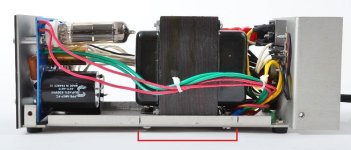
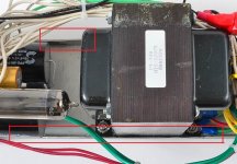
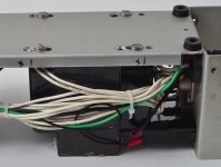
In an update from the mutual friend, it turns out that the slightly oversized Heyboer transformer was made to fit into the PSU case by trimming the rims with a Dremel and drilling new holes in the bottom in order to shift the new transformer just enough to clear the rectifier and fuse holder.
My friend forwarded the photos below and wrote, "Note the highlighted vertical marks in the first photo where the rim had to be modified. In the second photo, you can just about make out where Joe used a Dremel to cut away part of the rim. The third photo shows where he drilled new mounting holes in order to slide the replacement over a bit."
So, be prepared to do a bit of modification to the metal enclosure in order to make it work.
RC
That's larger than the one I used from Heyboer.
Still, minor modifications. It's probably just the closest larger standard core size available as Counterpoint made their own. Probably a non-standard size originally.
I would highly recommend using Heyboer from replacement Counterpoint transformers. Thanks for the info RC.
Still, minor modifications. It's probably just the closest larger standard core size available as Counterpoint made their own. Probably a non-standard size originally.
I would highly recommend using Heyboer from replacement Counterpoint transformers. Thanks for the info RC.
- Home
- Amplifiers
- Power Supplies
- Rebuilding Counterpoint SA-5.1 PSU