I have done some more work on my CFA pre-amp. I have got the distortion down to 380 parts per billion.
Its important that resistors R1, R2 R3 and R4 are matched - if you have a worst case resistor delta of 1 % in all the wrong direction distortion goes to about 2ppm.
The front end bias resistors R13, R14, R21 and R22 are much less sensitive and worst case absolute values based on 1% resistors give about 20ppb increase in distortion. In terms of powser supply rejection, this circuit will tolerate about 1mV reipple before it intrudes on the distortion performance. A series/shunt regulator will fix this easily.
I tried replacing Q3 and Q1 with a JFET's. The distortion increases to about 10ppm, but of course, you get th e excellent low bias input advantage. Problem is, matched JFET's are becoming rare and heading towards obseletion.
It goes without saying that the transistors should be carefully matched - including 're for the front end devices. Might be a good application for the THAT matched N and P devices they have.
I'll attach the FFT plot in the next post. It looks fairly clean to me with a hint of 2nd and 3rd and nothing after that.
Attachments
BTW, th e abov e simulations were done at supply rails of +-25V.
If the rails are raised to +-35, the distortion goes to 190 parts per billion. There is no 2nd and only a hint of 3rd.
It would be interesting to build this with THAT devices and also with standard BCxxx devices and compare the performance.
If the rails are raised to +-35, the distortion goes to 190 parts per billion. There is no 2nd and only a hint of 3rd.
It would be interesting to build this with THAT devices and also with standard BCxxx devices and compare the performance.
Bonsai said:Anatoly,
please help me to understand your objections to IC op-amps (I have no objections to either IC op-amps or discretes designs). I'd like to understand why an op-amp optimised for audio performance is inferior to a discrete solution. Lets do it like this - score 1 for better and 0 for worse
My reference op amps are LM4562, AD479 and venerable NE5532.
Spec/Feature Discrete Op-amp
CMRR 0 1
Distortion THD 20 0 1
Distortion IMD 0 1
Distortion PMD 0 1
Noise 1 (only just) 0
PSSR 0 1
Slew-rate 0 1
Output Drive 1 0
Bandwidth 0 1
DC performance 0 1
*Ease of use 0 1
*Cost/Performance 0 1
* optional and not really important if we are talking about cost no object
Feel free to modify as you see fit.
Once we have a few of these down on paper, maybe we can start to understand where to look as to the reasons why one is better than the other
What is your reference for discrete solutions?
Discard requirements for CMRR and DC performance and you have flexibility to get other parameters as good as desired. Including ease of use.
")
Edit: I myself have no objections against opamps when their usage leads to optimal results.
Here is an example:

Bonsai said:You pick the reference. Only criterion is that its commercially avaiable.
No problem. As soon as I get satisfied by production expenses it will be commercially available, because of a strange thing: performers for thousands can't afford what audiophiles can for themselves and few guests.
Wavebourn said:
No problem. As soon as I get satisfied by production expenses it will be commercially available, because of a strange thing: performers for thousands can't afford what audiophiles can for themselves and few guests.
Edit: Wait... Blowtorch preamp for example was available 18 years ago.
Bonsai said:I have done some more work on my CFA pre-amp. I have got the distortion down to 380 parts per billion.
--------------
I'll attach the FFT plot in the next post. It looks fairly clean to me with a hint of 2nd and 3rd and nothing after that.
Bonsai,
http://www.diyaudio.com/forums/attachment.php?s=&postid=1602008&stamp=1220533712
your current feedback amplifier ( CFA )
----------------------------------------------------------------------------------
1. how much voltage gain
2. what load impedance
3. output voltage swing, nominally
4. the only thing I put a question for
is the unusual way you bias the cascode transistors in VAS.
I have never seen this before.
Can this really work?
If it does .. great
I might consider have a go at that Trick.-----------------------------------------------------------------------------------
Note: Your answers on Point 1, 2 & 3 are essential.
This tells us what job the amplifier actually does:
How much it is set to increase voltage + current = power
.... and we can say the degree of signal amplification done
When we compare ampifiers we should do as Mr Juhn Curl says:
All other things equal !!!!!!!!!
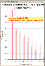
Now, people, I recon not many op-amps can be set to do an equal job to my 120 Volt Pre Amplifier.
Like 20 Vrms output into 1 kOhm at Voltage gain x20 ( +26 db )
Without almost no feedback .. and steadily and nice falling harmonics.Lineup 120 Volt preamp with very low feedback
I attach my FFT .. so we can compare with your FFT in post here above.
Attachments
Lineup,
1. The preampwill drive 600 Ohms with < 1ppm up to 2V pk to pk.
2. I've run simulations into 10K ohms 8Vrms at <20ppm; Inro 600 Ohms 5Vrms distortion is <30ppm at 20Khz
3. Open loop gain can be adjusted by R6. Set it to 100k and OL is about 60dB. Set it to 5k and its about 22dB. With CL gain at 9 db and loop gain at 13db, 20Khz is 0.01% at 2V out into 10k.
4. nominal output is 1VRMS, but 2Vrms is ok as well.
5. I hav e simplified the circuit and the diustortion is still <2ppm at 2V out
6. OL -3db is about 1Mhz - but this can be taylored by R6, C1 and the input filter.
7. The front end cascode bias. This really only helps if you are sub 1ppm and eant to go even lower. I used LED's because they are low noise. The merit of this approach is questionable, since 're matching and resistor matching as mentioned in my previous post are critical - you need really well matched components to acheive this - so it is in my view largely academic.
I've done some more work on this discrete op-amp and simplifed it considerably, and still got good performance:-
2.8V pk-pk 0.003% disti 20THD into 10k, .005% into 600 Ohms
and .02% at 16V pk to pk output
Output stays in Class A up to 16V pk to pk into 600 Ohms
+-15V rails
current consumption c. 24mA
Tolerates 10mV ripple on the supply rails without degradation in performance
Best of all - no caps in the signal path and rise and fall time of 100nS with no overshoot (10k load//2pF).
Bandwidth DC to 30Mhz
OLG is programmabe from 42dB max down to 20dB with 2 resistors
Reduced componenent count
I did the simulations with OLG of 22dB and CLG of 8db
Circuit attached. I am looking on the web for some matched transistors in SMD - I found NXP have got some. If anyone knows of any others for this project, let me know. Next step is to lay a board out - I'll post that up when its complete.
Attachments
- Status
- This old topic is closed. If you want to reopen this topic, contact a moderator using the "Report Post" button.
- Home
- Amplifiers
- Solid State
- Real Men Don't Use Opamps