I've always wondered what BSC, I like the idea of using ants.It's about baffle width and the space where the speaker is working. To calculate the F3 at the baffle step use 115/baffle width in metres.
I'll give you a visual example of baffle step using ants.
With a speaker against the wall (2PI space), picture the baffle covered in ants. As some ants escape to the back of the speaker they can't hide so you see them all (no baffle step reduction).
With a speaker in free space (4PI space), the escaped ants now can hide behind the box so you can't see them, only the remainder. That's the SPL reduction from baffle step.

Is it only the baffle width that's taken into account? Would the height of the baffle affect things also?
I remember seeing an online BSC calculator that asks for height here: Online Baffle Step Calculation but I'm not really sure of the maths this calculator is using.
Anyway I've tried adding some BSC a few minutes ago using the 115/width calculation and I can say has improved the sound from these speakers quite noticeably.
Here's my speaker:
An externally hosted image should be here but it was not working when we last tested it.
Here's filter settings on my DEQ:
An externally hosted image should be here but it was not working when we last tested it.
115/0.261 = 440.6 Hz (442 is the closest setting on my DEQ)
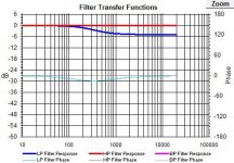
I'm using a 6db/octave low pass filter, can someone confirm I've got everything correctly set here? Thanks.
Is it only the baffle width that's taken into account? Would the height of the baffle affect things also?
I don't know if the height affects the BSC, but I think it was Thiele who wrote that you would get a better response if you had the box go all the way to the floor, even if it was just a smaller system (like a two-way or MTM).
I'm learning so much in such a short time, I feel realy blessed.
Just now I got the sound of my pc speakers to sound nice for the first time.
Little Logitechs, I'm loosing myself in the decay of the drumstick hitting the side of the snare on Brothers in arms now. I was just trying to apply some of the things that started to pop out at me, like placeing the satelites right up against the wall, the added some gain in the 2 octaves under the BSC knee on the EQ, with the bass knob on the back of the "sub" dialed to 0. Allthoug it still has a sweetspot the size of a melon, the sound is rather full, and it realy is hard to believe it comes from those tiny drivers. Of coarse we are not compareing to a true hifi set of speakers
Here is a link to a post I made comparing BSC before the amp vs after the amp. I call the latter 'shelving'. Response measurements were made that show the effect of each method on a vintage 2-way New Large Advent loudspeaker. Worth a view.
BSC vs Shelving - The Classic Speaker Pages Discussion Forums
Here is a link to the Basel BSC thread I referenced in the above link. It's become quite popular.
http://www.classicspeakerpages.net/IP.Board/index.php?showtopic=2692
BSC vs Shelving - The Classic Speaker Pages Discussion Forums
Here is a link to the Basel BSC thread I referenced in the above link. It's become quite popular.
http://www.classicspeakerpages.net/IP.Board/index.php?showtopic=2692
Last edited:
I've always wondered what BSC, I like the idea of using ants.
Is it only the baffle width that's taken into account? Would the height of the baffle affect things also?
I'm using a 6db/octave low pass filter, can someone confirm I've got everything correctly set here? Thanks.
The height of the baffle determines the vertical "step", the width the horizontal "step" frequency.
Distance to the floor and wall and cabinet depth also play into the depth of the step.
A six dB per octave LP filter set to 442 Hz would be about -30 dB at 14,000 Hz.
The graphic picture of your response does not look like a 6db/octave low pass filter, but looks about like what a baffle step compensation should look like. Whether it is correct (or needed) for your speakers and their position in the room could be measured, but not determined by looking at a DSP display.
Looks like you are using a shelving EQ :^).
Like a "loudness contour", that type of EQ often "sounds better", especially when listening at a lower level than the music was mixed at.
Art
I've tried adding some BSC
Since baffle step compensation is a compromise rather than a correction, it is worth trying a total of 4.5dB and 3dB as well.
The most uniform bass response comes from using 4 subwoofers (more is better but not necessary as 4 is usually sufficient) located in the 4 corners or the 4 midpoints of the room walls. This according to Harman International's web site based on the work of Floyd Toole. Of course these give more bass reinforcement than moving the speakers away from the walls. The corners restrict radiation to only pi/2 steradians and mid wall placement on the floor restricts radiation to pi steradians.
I think it as width around the sides, as the ants can't go through the floor to go around the box verticaly....
The woofer I want to use has a bit of a riseing response as you go up in frequency with a particularly bad 12db bump just a short distance after the crossover point.
Do I understand correctly that with active CO we would boost the lower frequencies rather than cut like with passive CO?
Would if crossed over, the slope follow its original trend, just x-db down, or does it just smoothe out...? Getting a scope soon then I can ask less questions.
Last edited:
The floor, yes, except where stands are used , but vertically (above)? Why not?I think it as width around the sides, as the ants can't go through the floor to go around the box verticaly....
This sounds like cone breakup, and if so you are right to cross before it. It needs to be fixed in its own right which you can either do separately or together with other fixes.a particularly bad 12db bump just a short distance after the crossover point.
When active, this point largely becomes moot. (For what it's worth, I'd use passive components in my line level circuits before the amp.) The point that has been raised, as far as I can see it, is that with a pre amp correction there will be no passive components wasting the amp's power.Do I understand correctly that with active CO we would boost the lower frequencies rather than cut like with passive CO?
To me this is irrelevant as either way, the power amp will always play the bass at the same level for a given power output. Since passive and active systems are both worthy and viable it becomes your choice.
Applying active corrections will not affect how passive components work with the speaker. They will simply add to the overall effect.Would if crossed over, the slope follow its original trend, just x-db down,
Because they can not reach the front again?The floor, yes, except where stands are used , but vertically (above)? Why not?
115/0.261 = 440.6 Hz (442 is the closest setting on my DEQ)
I'm using a 6db/octave low pass filter, can someone confirm I've got everything correctly set here? Thanks.
That looks right as it is lifting the bottom end (or reducing the upper end) (RL filter) unlike a 1st order filter (L only) which would continue to roll off through the higher frequencies. Baffle step is the inverse of what you see there. The amount required depends on the location, speaker and taste.
This can also be achieved by use of a 0.5 woofer to create a 2.5 way speaker which is a great solution in free space as it provides full BSC.... it replaces what goes MIA. You can test this by using a single 2-way in free space and then using the other 2-way under the first speaker with the woofer working only but adding a 6dB filter.... 3.8mH to 5.6mH inductor in series directly to the woofer. Listen to the difference as it's significant. The actual final value would be different but close enough for a test.
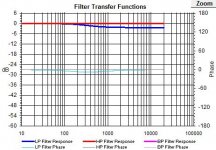
Compare the shape of yours to the graphs of filter transfer function of an in series RL parallel contour network (BSC). The first has high BSC and the second only half.
Attachments
The floor, yes, except where stands are used , but vertically (above)? Why not?
I may be wrong, but I think it's determined by the smallest baffle dimension which is usually the baffle width. It's the same when you design OB baffle speakers as you calculate Fe, Fp on the smallest path from the centre of the driver from the front to the rear.
Agreed, the smallest dimension is the most significant as can be confirmed by assessing the baffle radially. Or in other words if you compare a tall and narrow cabinet to a very tall and narrow cabinet there will be little difference.I may be wrong, but I think it's determined by the smallest baffle dimension which is usually the baffle width.
Think of the difference between DC and AC. The sound does not reach around one side and come back to the other (even though it also does, but that's another story).Because they can not reach the front again?
OK, I'm going to break my head if I don't get some assistance it seems.
I hope someone is bored enough to help me get a woofer a box and a tweeter to co-operate with each other.
I will post what I have so far in terms of raw data.
The box is 75L and still creates a bit of a bump in the bass region, due to the driver being more suitable for a car I think. does not sound bad, and goes low enough for my use generaly. (and thats in a box according to WinISD, that realy screws things up). I'll add the sugested dimensions so that BSC can be incorporated.
I'd like suggestions for, driver and tweeter placement,
crossover filters, points and slopes.
Attenuating the 4ohm tweeter to work with the 8ohm driver.
and BSC.
So here is the data attached: for the box and woofer, I'll do tweeter in seperate post so you can open two images at the same time.
Attachments

That woofer seems a little undersized for the box
I mean ,look at the basket holes ...(I'm amused by the new basket designs with nearly zero resistance to the cone's movement). You could even 'stress' the Damping Factor by covering the basket with a soft tissue .
I would start with an H-frame design or U-frame (OB )....thus needing a midrange .
I mean ,look at the basket holes ...(I'm amused by the new basket designs with nearly zero resistance to the cone's movement). You could even 'stress' the Damping Factor by covering the basket with a soft tissue .
I would start with an H-frame design or U-frame (OB )....thus needing a midrange .
Last edited:
I have a midrange set available, but have no TS params on them, so it would be very bad guesswork. I have seen these drivers used in 50L enclosures too, but according to winISD there is more than a 2db hump in the bass then.
The good news is that I found a place to repair my scanspeak 18W4585K's, but it will still be a little while before that happens...not exactly cheap.
So it will only be temporary speakers for learning, I have some 12mm marineply in the roof I can use so long to make boxes.
The good news is that I found a place to repair my scanspeak 18W4585K's, but it will still be a little while before that happens...not exactly cheap.
So it will only be temporary speakers for learning, I have some 12mm marineply in the roof I can use so long to make boxes.
Last edited:
The more ,the merrier !!
If you have some crossover components around ,it would be nice to build an 'experimental set' ...
)
A quick listening test would tell you if driver's sensitivities could be well aligned or if it's a totally no-no.
If you have some crossover components around ,it would be nice to build an 'experimental set' ...
I made an H-frame using 3mm heavy cardboard (the one used for the back of the ...framesI have some 12mm marineply in the roof I can use so long to make boxes.
)A quick listening test would tell you if driver's sensitivities could be well aligned or if it's a totally no-no.
- Status
- This old topic is closed. If you want to reopen this topic, contact a moderator using the "Report Post" button.
- Home
- Loudspeakers
- Multi-Way
- Quick baffle step correction question.